
The Wellhead in Oil and Gas: Its Components, the Christmas Tree, and Where Threads Meet Flanges
The wellhead is where the threaded steel inside a well meets the bolted steel on top of it. This page walks the stack from the casing head to the tree, explains what each section does and how it is joined, and shows which of its joints were made up on a bench before the rig…
A wellhead in oil and gas is the pressure-containing assembly at the top of a well that suspends the casing and tubing strings, seals the spaces between them and carries the blowout preventer during drilling or the Christmas tree during production. It is built in three sections, casing head, casing spools and tubing head, and it is where the well’s threaded tubulars meet its bolted, flanged surface equipment.
At a glance
| What it does | Hangs every casing string and the tubing from surface, seals each annulus, gives access to those annuli through side outlets, and provides the flanged connection for a BOP stack during drilling and a tree during production |
| The components | Casing head on the surface casing; one casing spool per additional casing string, each with its hanger; tubing head with the tubing hanger, topped by an adapter and the tree |
| How it is joined | Threads below and inside: casing head to surface casing, mandrel hangers to casing, tubing hanger to the hanger pup. Flanges and studs above: head to spool, spool to tubing head, adapter to tree. Slips where a hanger grips the pipe instead of threading onto it |
| The governing document | API Specification 6A for wellhead and tree equipment, with rated working pressures from 2,000 to 20,000 psi, product specification levels and material and temperature classes |
| Decision this page supports | Reading a wellhead for its threaded joints, so a shop knows which of them it makes up on a bench, which the rig makes up, and which are bolting work it should leave alone |
Wellhead vs Christmas tree: what each one does
Every string run into a well has to hang from something at surface, and every annulus between those strings has to be sealed and reachable. The wellhead is the stack of steel that does both. It grows with the well: the casing head goes on when the surface casing is cemented, a spool is added each time another casing string is set, and the tubing head goes on at completion. During drilling the stack carries the blowout preventers; when the completion is landed the preventers come off and the Christmas tree goes on. The tree is often called part of the wellhead and it is not: the wellhead suspends and seals the strings, while the tree is the set of valves and the choke that control flow from the tubing, used only in production (Control Global, Wellheads and Christmas Trees).
For a workshop the distinction matters because the two are joined differently. The wellhead has threaded connections in it, to the casing and to the tubing, and those threads were made up somewhere. The tree is flanged and studded from top to bottom, and nobody makes up a tree on a bench. Reading the stack joint by joint, which is what this page does, is the way to see where a bench has a part in it and where it does not.
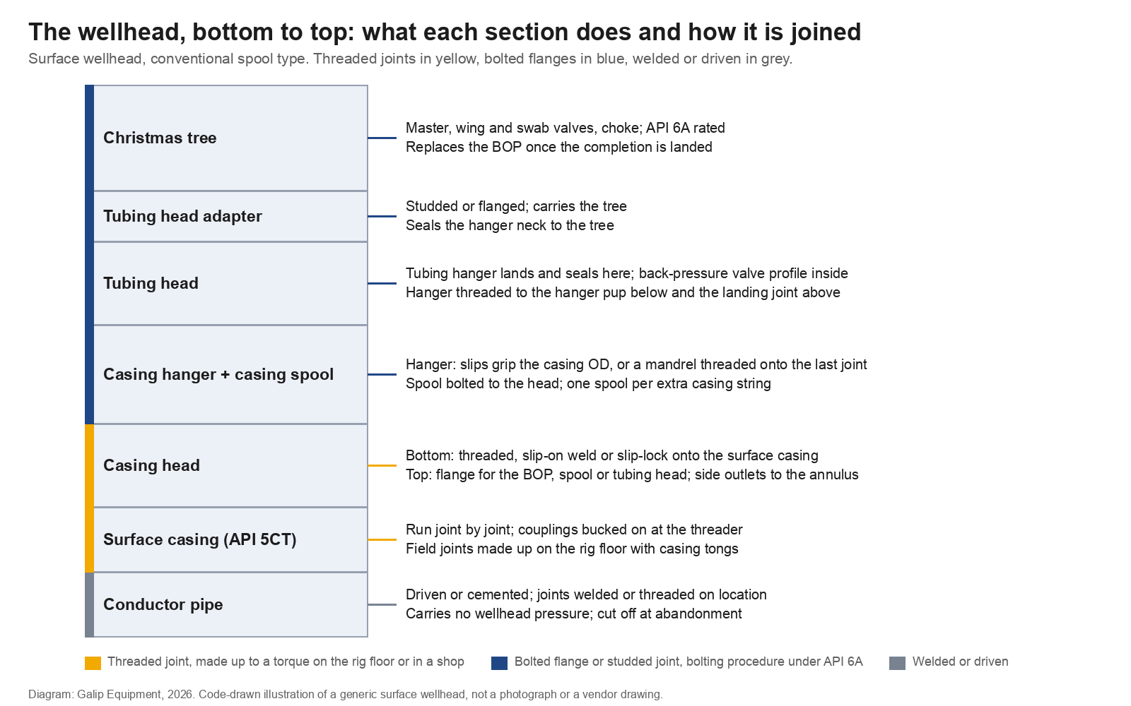
Wellhead components, bottom to top
| Section | What it does | How it is joined, and where that joint is made |
|---|---|---|
| Casing head | The lowest pressure-containing part, fitted to the surface casing. It supports and packs off the next casing string, gives the first flanged connection for the BOP stack, and provides side outlets to the surface casing annulus (Tiger Valve, Components of a Wellhead) | Bottom connection threaded onto the surface casing, slip-on and welded, or slip-locked with a mechanical grip; the threaded version is made up on location with casing tongs. Top connection flanged |
| Casing hanger and casing spool | The hanger carries the weight of a casing string and seals its annulus; the spool houses the hanger, carries the next BOP connection and gives side outlets to that annulus. One spool per string after the surface casing (ScienceDirect, Casing Spool) | Slip hangers grip the outside of the casing and need no thread; mandrel hangers are threaded onto the top of the last joint, like a coupling, and are made up on the rig floor as the string is landed. The spool itself is bolted to the head below and the spool or tubing head above |
| Tubing head | Houses the hanger that suspends the tubing string, seals the tubing-casing annulus and carries a profile for a back-pressure valve so the tree can be removed with the well plugged. An adapter on top carries the tree | The hanger is threaded to the tubing below, usually through a hanger pup joint prepared in advance, and to a landing joint above for running. The head, adapter and tree are flanged or studded |
Below the casing head sits the conductor, driven or cemented in the first few tens of metres, carrying no wellhead pressure and often welded rather than threaded. Above the tubing head sits the tree. Between those two limits the pattern is consistent: threads where a string has to be caught, flanges where two pressure-containing bodies have to be bolted together and taken apart again.
Hangers: slips, mandrels and the one threaded joint on the rig floor
How a casing string is caught at surface decides whether there is a thread involved. A slip-type hanger is a set of wedges with a seal that are placed around the casing in the bowl of the head or spool; the casing’s own weight sets the wedges, and the casing is then cut above the hanger and the next spool bolted on. No thread, and it works on a string that is stuck and cannot be moved to the exact height. A mandrel hanger is a machined body with a sealing surface outside and a casing thread inside, threaded onto the last joint before it is run, so that the string lands on a shoulder in the head and seals without the BOP being lifted. Multibowl or unitized wellheads use a fixed landing shoulder in one housing and stack mandrel hangers on it, which is why they have become standard where wells are drilled in numbers: the preventers stay on, and each string is landed and sealed from inside (IPTC 2024, Compact Unitized Wellhead System for Unconventional Wells). Offshore, the subsea wellhead applies the same idea in a single high-pressure housing on the seabed.
The mandrel hanger’s thread is the one wellhead connection that is made up on the rig floor as a tubular. It is a casing thread, API or premium, on a heavy body, made up with the casing tongs to the connection owner’s torque at the end of the run, and recorded like any other casing connection by the crew described in tubular running services. The joint below it, the last casing coupling, was bucked on at the threading shop. The joint above it is a flange.
API 6A: the ratings behind the stack
Everything from the casing head up is specified under API Specification 6A, the standard for wellhead and tree equipment, whose purpose is to make that equipment interchangeable and safe across suppliers. It fixes the rated working pressures the equipment is designed for, 2,000, 3,000, 5,000, 10,000, 15,000 and 20,000 psi, defines product specification levels that set how much testing and documentation a component carries, and sorts materials into classes according to the corrosiveness of the produced fluid and temperature classes according to the service range (Introduction to API Specification 6A). The casing and tubing hanging from that equipment are specified elsewhere, under API 5CT and the connection licensors’ data, which is set out in API 5CT. The wellhead is the place where those two families of standard, and the two kinds of supplier behind them, physically touch.
That touch is also a handover of responsibility. The threads on the hanger pup and the mandrel hanger belong to the tubular standards and are made up to a recorded torque. The flange studs belong to the wellhead standard and are tightened to a bolting procedure. A wellhead crew carries torque wrenches; a completion shop carries a bench. Each should know where the other’s work starts.
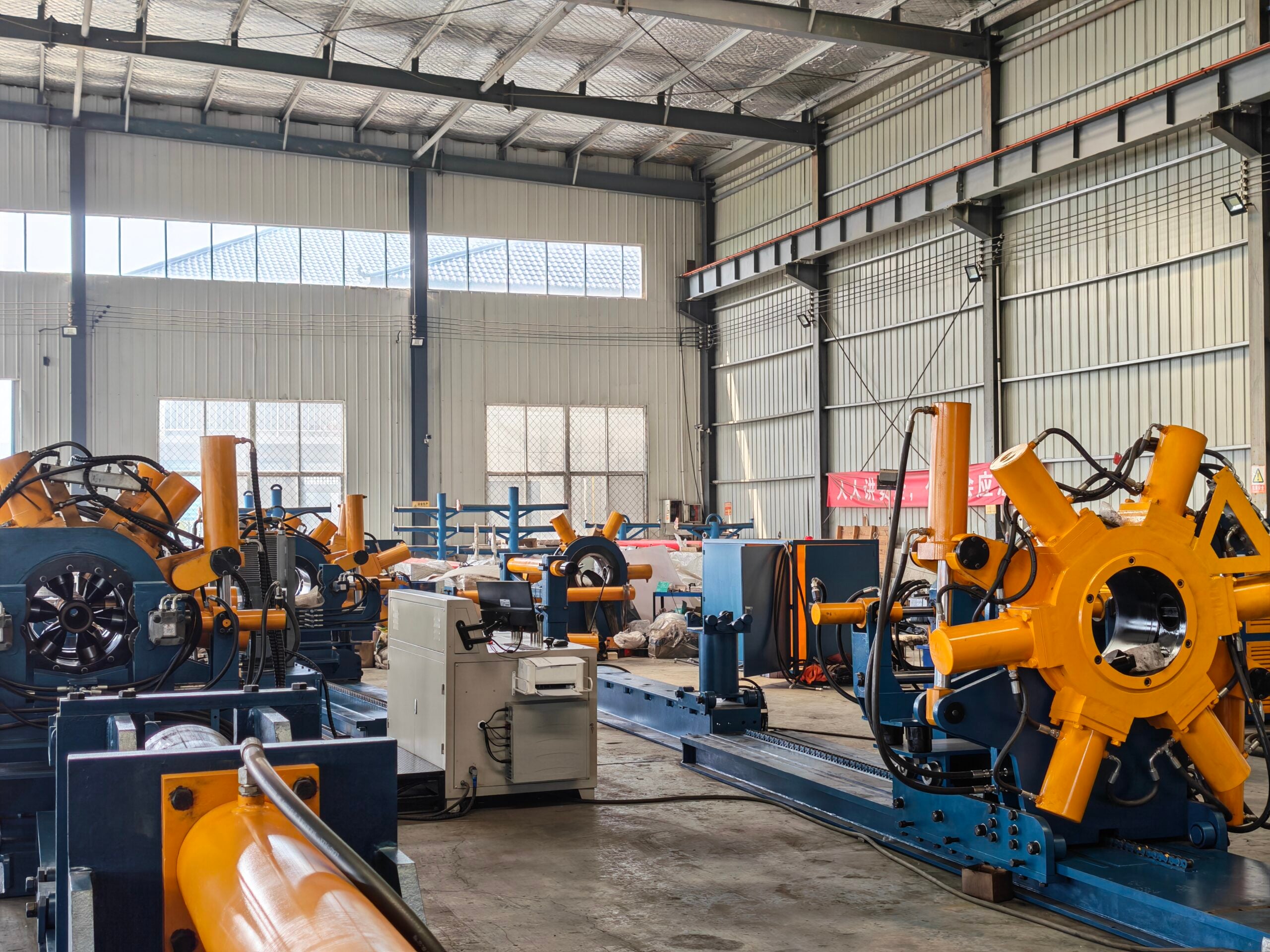
Where threads meet flanges: the hanger joint
The hanger in the tubing head is the component to look at if the question is where a bench has a part in the wellhead. It is a short, solid body that lands in the tubing head, seals the annulus, and is threaded top and bottom: below to the tubing string, above to the landing joint the rig uses to run it. The thread below is rarely made up straight onto a full-length joint of tubing. The usual practice is a hanger pup, a short tubing joint made up to the hanger’s bottom thread in advance, so that the string can be spaced out to land the hanger at the right height. On a premium completion the pup carries the same connection as the rest of the string, and the make-up to the hanger has to meet the same window.
That make-up is shop work. The hanger body is machined, sealed and profiled, with a back-pressure valve profile inside and often control-line penetrations for the safety valve, and none of it should be marked by a jaw or strained by a tong on a rig floor. In a completion shop the hanger and pup go onto a horizontal hydraulic bucking unit, clamped on jaws chosen for the hanger body, rotated at low speed to the connection owner’s shoulder and torque, with the trace recorded and tagged with the hanger’s serial number. The rest of the completion accessories are prepared the same way, as set out in well completion explained; the hanger pup is simply the last of them, and the one whose make-up the wellhead will be standing on for the life of the well.
The landing joint on the other side of the hanger is the opposite case. It is a running tool, made up on the rig floor, used once to land the hanger and then backed out, and its torque is whatever lets it carry the string and release cleanly. A shop has no part in it. The distinction is worth keeping clear in an enquiry: a completion shop asking about hanger make-up means the pup side, and the machine is specified for a hanger body, a premium connection and a record.
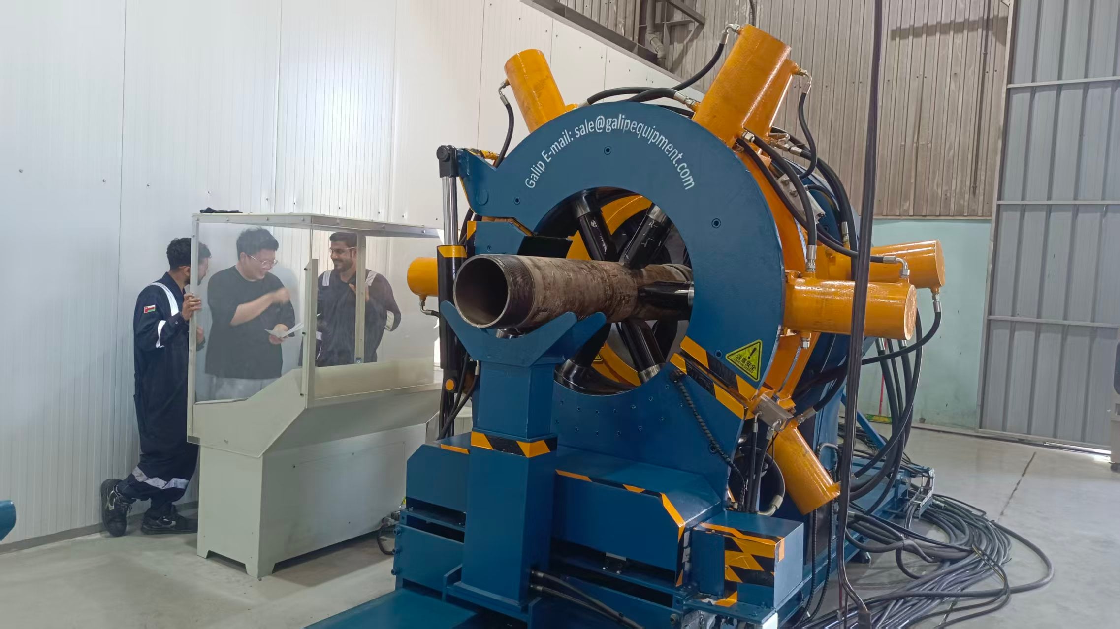
The records that meet at the wellhead
Three records come together where the tree is landed. The threading shop’s torque-turn record for every casing and tubing coupling, produced on a bench. The rig’s torque-turn record for every joint-to-joint connection and for the mandrel hanger, produced by the running crew. And the wellhead crew’s bolting record for every flange and stud from the casing head to the tree, produced to a procedure and a calibrated tool. An integrity audit will ask for all three, and the one most often missing is the first, because the shop that made up the coupling or the hanger pup is two companies away from the operator.
| Joint | What is recorded | What the shop should hold |
|---|---|---|
| Casing and tubing couplings | Make-up torque and the torque-turn trace per coupling, at the threader | The trace tagged to the pipe heat and joint number, with the sensor calibration certificate behind it |
| Hanger pup to the hanger | The trace for that one make-up, at the completion shop | The trace tagged to the hanger serial, the connection, the compound and the operator, filed with the completion |
| Mandrel hanger to casing; joint-to-joint connections | The rig’s torque-turn record, by the running crew | Nothing; the shop only needs to know the rig’s record exists and that its own record matches the same torque window |
| Flanges and studs, head to tree | The bolting record per joint: pattern, passes, target, tool and calibration | Nothing; this is the wellhead crew’s work and the rules are those described for flanges in downstream oil and gas |
The thread records all stand or fall on the calibration of the bench that produced them, and the chain that keeps that calibration traceable is set out in torque and load calibration. A wellhead sees that chain once, at the moment the hanger lands, and then relies on it for decades.
The wellhead over the life of an oil and gas well
The stack is built during drilling, completed when the hanger lands, and then sits under the tree through production. It is opened again at every workover: the tree comes off, a BOP goes back on the tubing head, the hanger is pulled with the tubing, and the sequence runs in reverse when the string is re-run; the page on workover rig operations follows the tubing from there. At the end of the well’s life the wellhead is removed in the last phase of plug and abandonment, cut below ground or mud line with the casing it stood on, and goes to a wellhead shop for refurbishment or to scrap. A refurbished wellhead is a flanged, machined, pressure-tested assembly; the only threads a refurbishment shop handles are outlet and test-port threads, and nothing in it is bucking work.
The wellhead is upstream equipment throughout, the surface end of the drilling and completion phases described in upstream oil and gas. Wellhead manufacturers and the crews that install them are a supplier base of their own, with their own standard, and a bucking unit supplier’s part in their world is confined to the one threaded joint that lands in the tubing head.
When another page is the better start
A wellhead engineer selecting a system, conventional, multibowl or subsea, pressure rating, material class, is working to API 6A and the wellhead supplier’s catalogue, and this site adds nothing to that choice. A completion shop that already prepares hanger pups should go to the bucking unit product page and the acceptance checklist, and should ask specifically about jaws for hanger bodies and low-speed shoulder control for premium connections. A reader whose question was about the completion string as a whole should start with the completion page. And anyone asked to torque a flange should be reading a bolting procedure and ASME PCC-1, not a page about threaded make-up.
The usual limit holds. Torque values for hanger and casing connections belong to the connection owners, pressure ratings and bolting values to API 6A and the wellhead supplier. This page describes which joint is which and who makes it; the numbers come from the documents that own them.
Frequently asked questions
What is a wellhead in oil and gas?
The pressure-containing assembly at the top of a well that suspends the casing and tubing strings, seals the annuli between them, gives access to those annuli through side outlets, and carries the blowout preventer during drilling or the Christmas tree during production. It is built in sections as the well is drilled: casing head, casing spools and tubing head.
What is the difference between a wellhead and a Christmas tree?
The wellhead hangs and seals the strings and is used from the first casing string onward, under the BOP during drilling and under the tree during production. The tree is the assembly of valves and choke bolted on top once the completion is landed, and it controls flow. The wellhead contains threaded tubular joints; the tree is flanged and studded throughout.
What are the main wellhead components?
The casing head on the surface casing; a casing hanger and casing spool for each further casing string; the tubing head with its tubing hanger; and the tubing head adapter that carries the tree. Hangers are slip type, gripping the pipe, or mandrel type, threaded onto the last joint. Multibowl wellheads put several hangers in one housing.
What is a casing head?
The lowest pressure-containing part of the wellhead, fitted to the surface casing by a threaded, slip-on weld or slip-lock bottom connection. It supports and packs off the next casing string in its bowl, provides the first flanged connection for the BOP stack or the next spool, and has side outlets for access to the surface casing annulus.
What does API 6A cover?
Wellhead and Christmas tree equipment: heads, spools, hangers, adapters, valves and chokes. It sets rated working pressures from 2,000 to 20,000 psi, product specification levels that define testing and documentation, and material and temperature classes for the service. The casing and tubing hanging from that equipment are covered by API 5CT and the connection owners’ data instead.
Which wellhead connection is made up on a bucking unit?
The hanger in the tubing head to its hanger pup joint. The hanger is a machined, sealed body with a back-pressure valve profile and often control-line penetrations, and its bottom thread is made up to a short pup in a completion shop, on a horizontal bench, to the connection owner’s torque with a recorded trace. Mandrel hanger and casing head threads are made up on location; everything above is bolted.
Send the hanger joint, not the wellhead drawing
A completion shop enquiry about hanger make-up is answered from the joint itself. The useful set for a bucking unit quotation is: the tubing sizes and connection families run, the hanger types and body dimensions handled, the pup joint lengths, the connection owners’ make-up torques for the hanger thread, whether control-line penetrations or profiles need protecting in the clamp, the record format the operator and the wellhead supplier expect, the site power supply and a sketch of the bay. The Galip team quotes from that list and will say which jaw sets suit the hanger bodies.
The wellhead checklist
- Separate the wellhead, which hangs and seals the strings, from the tree, which controls flow; only the first contains threaded tubular joints.
- Read the stack bottom to top and mark each joint threaded, slipped, welded or flanged.
- Treat the casing head’s bottom thread and the mandrel hanger thread as rig-floor make-ups, recorded by the running crew.
- Treat the hanger pup to hanger make-up as shop work, on a bench, with a trace tagged to the hanger serial.
- Treat every flange and stud from the casing head to the tree as bolting work under API 6A and a bolting procedure.
- Match the shop’s torque window to the connection owner’s data, the same window the rig uses on the joints above and below.
- Keep the shop trace, the rig record and the bolting record together for the well; the audit asks for all three.
- Expect the stack to be opened at every workover and removed at abandonment, and keep the hanger make-up record for that long.
Expert Consultation
Need more information on optimizing your equipment performance? Our engineering team is available for technical consultations.
Request a Quote
Tell us about your requirements and our engineering team will prepare a detailed proposal with specifications, pricing, and delivery timeline.
