
Plug and Abandonment: What Happens to a Well at the End, and to the Pipe That Comes Out of It
A well that can no longer pay for itself is plugged and abandoned. This page explains the three phases of a permanent abandonment, the barriers that must be set, and follows the tubing, casing and wellhead that come out of the hole to the yard that receives them.
Plug and abandonment is the permanent closure of a well that has reached the end of its life: the tubing is pulled, permanent barriers are set across the reservoir and any other flow zones, casing is cut and recovered where it must be, and the wellhead is removed. Everything that comes out of the hole goes to a yard, and most of it arrives needing a break-out before anything else.
At a glance
| What it is | The last phase of a well’s life: isolating every pressured or fluid-bearing zone from every other zone and from surface, permanently, then removing the surface equipment and restoring the site |
| The three phases | Reservoir abandonment, intermediate abandonment of the overburden, and wellhead and conductor removal, in the framing used by the UK industry’s guidelines and by NORSOK D-010 |
| The barriers | Two independent permanent barriers across each zone, usually cement, verified; placed by plug, by perforate-wash-cement or by section milling where the annulus has no cement |
| What comes out | The completion string and its accessories, cut casing where the string was pulled, the wellhead and the conductor; all of it to a yard, graded for reuse, downgrade or scrap |
| Decision this page supports | Reading an abandonment programme for the break-out and reconditioning workload it generates, and sizing the yard equipment behind it from that load rather than from a make-up table |
What plug and abandonment is
Every well is drilled with its end in mind. When production no longer pays for the cost of keeping the well safe, or the field is being decommissioned, the operator has to leave the hole in a state that will never let formation fluid reach another formation, an aquifer or the surface, and will never need maintenance again. That is plug and abandonment: permanent plugs set at the depths the regulator specifies, the completion and some of the casing removed, the wellhead taken off, and the site returned to whatever it was. The UK industry body publishes a guidelines package for exactly this, covering the minimum criteria for isolating formation fluids within the wellbore and from surface (OEUK, Guidelines for the Abandonment of Wells), and the Norwegian NORSOK D-010 standard sets out the same two-barrier logic in detail.
The scale of the work is now large enough to be its own industry. In the UK sector alone, operators worked on 257 wells in 2025 and brought 114 of them to final abandonment, with a backlog of roughly 500 wells still awaiting it and more than 1,000 forecast for decommissioning over the next five years (NSTA, UKCS Decommissioning Cost and Performance Update 2026). Onshore in the United States the problem is older and larger: the Department of the Interior counts around 157,000 documented orphaned wells, and the federal programme funded in 2021 had plugged more than 11,000 of them by the end of fiscal 2025 (DOI, Orphaned Wells Program FY 2025 Report). Each of those wells had a string of threaded steel in it, and most of that steel came out.
That is the angle this page takes. The sector guides explain abandonment from the well engineer’s chair, barrier by barrier. The workshop sees it from the other end, as racks of pulled tubing, cut casing and stripped wellheads arriving by truck, and as the heaviest break-out work in the industry. Both views are correct, and a yard that serves abandonment contractors needs to understand the first in order to plan for the second.

The three phases of a permanent abandonment
The UK guidelines divide the job into three phases, and the division is useful because each phase sends something different to surface.
| Phase | What is done at the well | What comes out, and where it goes |
|---|---|---|
| Phase 1: reservoir abandonment | The well is killed and the tree removed. The tubing is released from the packer, or cut above it if it will not release, and pulled. Primary and secondary barriers are set across the reservoir, usually cement plugs placed on a mechanical base, and verified | The production tubing, in full or in part, to a pipe yard. Packers, mandrels, nipples and safety valves to a service shop, most of them for the last time. Nothing is recovered from the reservoir section itself |
| Phase 2: intermediate abandonment | Any fluid-bearing or pressured zone in the overburden is isolated with its own two barriers. Where the casing has no cement behind it, the casing is cut and pulled so that a plug can be set across open rock, or the annulus is treated by perforating, washing and cementing. A surface plug is set | Cut casing joints, often in short lengths, to the yard for sorting: a few reconditioned, most downgraded or scrapped. Stuck or collapsed strings go straight to scrap. The cutters, spears and jars go back to their service centre |
| Phase 3: wellhead and conductor removal | The casings and wellhead are cut below ground or below the mud line, the conductor is pulled or cut, and the site is restored | The wellhead to a wellhead shop for refurbishment, or to scrap. The conductor and surface casing to scrap. Any connection still intact on recovered pipe has to be broken out on a bench before the pipe can be graded |
Offshore in the United States the federal regulation sets the same shape with its own numbers: perforated intervals that are still open must be squeezed or covered by a plug extending at least 100 feet above and below them, and wellheads and casings must be removed to at least 15 feet below the mud line (30 CFR 250 Subpart Q, Decommissioning Activities). Onshore rules vary by state and country, and the operator’s programme is written to the regulator that owns the well. This page does not substitute for any of them.
Barriers: the part of the job nobody sees again
A permanent barrier is a seal across the full cross-section of the well, including every annulus, that will hold for geological time without maintenance. Cement is the usual material, and the rule in every modern regime is two of them, independent, across each zone that could flow. Where the casing has good cement behind it the plug can be set inside the casing. Where it does not, the engineer has a choice: cut and pull the casing so the plug sits against rock, mill a window through the casing and cement across it, or perforate the casing, wash the annulus clean and cement through the perforations. That last method, perforate-wash-cement, has been qualified as an alternative to section milling for establishing a NORSOK-compliant barrier, and it avoids the swarf and the time that milling produces (Havtil, PWC Qualification Process). The two-barrier rule that governs them is explained in well integrity. What a primary cement job does, and why its sheath can fall short, is explained in well cementing and float equipment.
The choice matters to a workshop for one reason: it decides how much casing comes out. A cut-and-pull programme sends casing to surface; a perforate-wash-cement programme leaves it in the ground. Two wells of the same design can therefore produce very different truckloads, and a yard quoting for an abandonment campaign should ask which method the programme uses before it estimates the tonnage.
Pulling the completion: the first thing to reach the yard
The tubing comes out first, and it comes out in the worst condition of its life. It has carried produced fluid for years, often with water, sand, scale and corrosive gas; its couplings have been loaded, heated and cooled through every shut-in; and its accessories, the packer, the mandrels, the nipples, are still threaded into it. If the packer releases, the whole string is pulled joint by joint on a workover rig or a platform rig. If it does not, the tubing is cut above the packer and the lower part stays in the hole to be cemented over. Either way what reaches surface is a string of used tubing with its couplings made up tight, and the sequence that follows is the one described in workover rig operations: to the pipe yard, every joint broken out, cleaned, inspected, drifted and graded.
Abandonment tubing differs from workover tubing in one respect. It is not going back into that well, so the yard’s question is not whether a joint is fit for re-running but what it is fit for at all. The used-pipe trade grades recovered tubulars by wall loss into bands, and only the top bands are considered for further well service; the rest goes to water wells, structural and fencing use, or scrap (Pipe and Metal Center, Repurposed Oilfield Materials). A joint that is to be re-coupled for any further pressure service gets a new coupling made up to the manufacturer’s torque and a record; a joint bound for a fence line gets its coupling broken off and nothing else. The break-out happens in both cases.
The accessories take the path described in well completion explained, with a difference: most of them will not be redressed for reuse. A packer that has been set for fifteen years in a well that is now closed is usually stripped for its reusable parts and scrapped. The threaded joints on it still have to be broken to get at those parts, and they release no more easily than the tubing’s.
Cutting and pulling casing: the heaviest pipe in the yard
Casing is a different proposition from tubing. It is larger, heavier, cemented for part of its length, and was never designed to come out. Where the programme requires it, the string is cut above the cement top and pulled with a spear; where the annulus has settled solids, partial cement or collapsed formation behind the pipe, the cut section sticks, and the crew either jacks it free, cuts it into shorter lengths over several trips, or gives up on recovery and leaves it for a barrier to be set through. Combined cutting and pulling tools now do the cut and the pull in one trip, and downhole jacking tools have been developed for strings that a rig’s top drive cannot lift (Weatherford, Well Abandonment and Slot Recovery).
What reaches the yard from that work is a mix rather than a rack of matched joints: full joints with intact couplings from the upper string, cut lengths with a coupling on one end and a bare cut on the other, and sections with cement still clinging to the outside. The yard sorts it by what can be done with it. Full joints with sound connections can be inspected and, occasionally, reconditioned for a low-pressure use; cut lengths go to structural use or scrap; cemented sections are scrap after the cement is knocked off. The couplings on the first two categories have to come off, and casing couplings on recovered pipe are the heaviest break-outs a yard sees.
The conductor and surface casing from Phase 3 are simpler. They are cut, lifted and scrapped; nobody reconditions a conductor. The wellhead that sat on them goes a different way: a wellhead is a flanged and bolted assembly rather than a threaded tubular, and its disassembly is bolting work of the kind described in downstream oil and gas, followed by a refurbishment shop or the scrap pile. What that assembly is, section by section, is in what is a wellhead.

The yard that receives the pipe
Put the three phases together and the yard’s workload has a clear shape. Nearly everything arrives made up, and nearly all of it has to be broken out before anything else can be done with it: tubing couplings, casing couplings, accessory connections, the odd fishing tool. The joints are older, more corroded and more heavily loaded than anything from a workover, and the proportion heading for scrap is far higher, which changes the economics of the bench. A workover yard breaks out in order to re-couple; an abandonment yard breaks out in order to sort, and only re-couples the minority that will see pressure again.
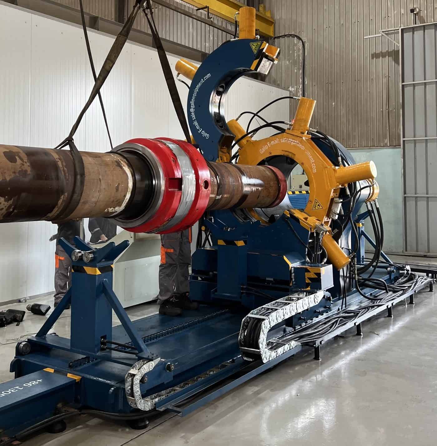
That is why the machine in an abandonment yard is specified from break-out, and why many such yards run a dedicated breakout unit rather than a general-purpose make-up bench. Galip’s largest breakout unit frame, the DZZR-V3518, is rated to 199,000 ft-lb of break-out torque against 150,000 ft-lb of make-up, and that asymmetry is the design argument: the machine exists for joints that need more torque to release than they ever took to make. The reasons a used connection behaves that way are set out in what is breakout force.
Three features matter more on recovered pipe than on new. The first is the jaw package. Corroded, pitted or ovalised pipe does not grip the way new pipe does, and a jaw set chosen for clean tubing will slip or crush; the yard chooses jaws and clamping pressure for the worst joint on the rack and accepts marks on pipe that is going to scrap anyway. The second is the clamping length. Cut casing lengths may be short, and a machine whose supports and clamps assume a full joint cannot hold them; the bench needs to clamp a short piece securely. The third is heat. Some connections will not release at any torque the bench can apply and are heated before the break-out, a practice a Galip customer in Thailand uses routinely on downhole tools returned from service, and the bench and its operators must be set up for it.
| Condition on arrival | What it does on the bench | What the yard should do |
|---|---|---|
| Heavy external corrosion or pitting | Jaws slip or dig in; clamping pressure that holds new pipe deforms this pipe | Select jaws for the worst joint on the rack; raise clamping pressure in steps with the trace watched; accept marking on scrap-bound pipe |
| Ovalised or crushed sections | The jaw set cannot close concentrically; the connection is loaded unevenly during break-out | Clamp away from the damaged section where possible; cut off and scrap sections that cannot be held |
| Short cut lengths from casing recovery | The piece is too short for standard supports; the clamp has little pipe body to grip | Specify the bench for the minimum length the campaign will produce; use a secondary clamp or fixture for stubs |
| Seized connections after years of service | Release torque exceeds make-up torque, sometimes by a wide margin; the trace shows a late, sharp break | Size the machine from break-out; apply heat under a written procedure where torque alone fails; record every attempt |
| Cement or scale on the body | Fouls jaws and supports; hides wall loss from inspection | Knock off and clean before the bench; inspect wall after cleaning, not before |
The record from the bench is as useful here as anywhere, and for a reason specific to abandonment. Recovered pipe that is sold on for further pressure service carries a liability, and a yard that can show the break-out trace, the inspection result, the drift, the new coupling and its make-up torque for each joint is selling reconditioned pipe. A yard that cannot is selling used pipe, at a different price. The drift step and its limits are covered in casing and tubing drift; the make-up record on the new coupling is the same one a threading shop produces, and the same hydraulic bucking unit produces it.
Where abandonment sits in the industry
Abandonment is the last phase of the upstream sector, after production has ended; the phase sequence is in upstream oil and gas, and the wider map of where the industry’s threaded steel lives is in upstream, midstream and downstream oil and gas. It is also the phase whose share of the sector’s work is growing fastest in mature basins, which is why decommissioning contractors, abandonment service companies and the pipe yards behind them have become a distinct customer group for break-out equipment. Enquiries for breakout units from workshops in the North Sea and Mediterranean regions, where abandonment campaigns are concentrated, arrive with that workload described: recovered pipe, seized joints, short lengths, and a break-out torque requirement first.
When another page is the better start
A well engineer designing an abandonment programme is working to the regulator’s requirements and the operator’s barrier philosophy, and nothing on this site adds to those; the OEUK guidelines, NORSOK D-010 and the applicable regulation are the documents that matter. A pipe yard that already knows its casing and tubing range and the break-out loads it sees should go to the breakout unit product page and its model table, and should raise jaw options for damaged pipe and clamping for short lengths before anything else. A yard whose work is mostly workover tubing that does go back in a well should read the workover page first, since re-coupling rather than sorting drives that bench. And a reader whose interest is in what a wellhead is and how it comes apart will find that in the coming page on wellheads rather than here.
The usual limit applies with extra force. Barrier depths, plug lengths and casing cut depths belong to the regulator and the programme. Break-out torques on recovered joints belong to no table at all; they are measured on the day, which is the strongest argument for recording them.
Frequently asked questions
What is plug and abandonment?
The permanent closure of a well at the end of its life. The tubing is pulled, permanent barriers, usually cement, are set across the reservoir and any other zone that could flow, casing is cut and recovered where a barrier must sit against rock, and the wellhead and conductor are removed below ground or mud line before the site is restored.
What is the difference between plug and abandonment and decommissioning?
Decommissioning is the whole programme of taking a field out of service: platforms, pipelines, subsea equipment and wells. Plug and abandonment is the well part of it, and usually the largest single cost. Onshore, where there is no platform, the two words are often used interchangeably for the same job.
What are the three phases of well abandonment?
In the UK guidelines’ framing: reservoir abandonment, where the completion is pulled and barriers are set across the reservoir; intermediate abandonment, where flow zones in the overburden are isolated and a surface plug set; and wellhead and conductor removal, where the surface equipment is cut away and the site restored. NORSOK D-010 follows the same logic.
What happens to the tubing and casing pulled during abandonment?
It goes to a pipe yard. Every joint is broken out from its coupling, cleaned, inspected and graded by wall loss. A minority is reconditioned and re-coupled with a record for further pressure service; more is downgraded to structural or water-well use; the rest, including cut and cemented casing lengths and the conductor, is scrapped.
Why is break-out torque the number that sizes an abandonment yard?
Because almost everything that arrives is made up and has spent years in a producing well, and a used connection needs more torque to release than it took to make up. Galip’s largest breakout unit frame is rated to 199,000 ft-lb break-out against 150,000 ft-lb make-up for that reason. A bench sized from make-up alone stalls on recovered casing couplings.
Is recovered oilfield pipe reused?
Some of it. The used-pipe trade grades recovered tubulars by wall loss, and only the best-condition joints are considered for further well service after inspection, drifting and re-coupling with a recorded make-up torque. Lower grades go to water wells, fencing and structural use, which still consumes large tonnages, and the worst goes to scrap.
Send the campaign, not the well count
An abandonment yard is quoted from what the campaign will send it. The useful set for a breakout unit quotation is: the casing and tubing sizes expected, the shortest cut lengths the recovery method will produce, the condition of the pipe (corrosion, ovality, cement), the highest break-out torque the yard has recorded or expects, whether any pipe will be re-coupled for further pressure service and therefore needs a make-up record, the monthly tonnage, the site power supply and a sketch of the bay. The Galip team quotes from that list and will say which frame covers the break-out figure and which jaw sets the pipe condition needs.
The plug and abandonment checklist
- Establish which barrier method the programme uses, cut-and-pull, section milling or perforate-wash-cement; it decides how much casing comes to surface.
- Expect the full completion string from Phase 1, cut casing from Phase 2 and the wellhead and conductor from Phase 3, and plan the yard for all three.
- Treat every recovered joint as a break-out first; sort for reuse, downgrade or scrap afterwards.
- Size the bench from the break-out torque on recovered connections, with the largest casing coupling as the governing case.
- Specify jaws and clamping for corroded, pitted and ovalised pipe, and clamping for the shortest cut length the campaign will produce.
- Write a heating procedure for seized connections before the first one arrives, and record every heated break-out.
- Re-couple only pipe that will see pressure again, to the manufacturer’s torque, with a record; break the coupling off everything else.
- Keep the break-out trace, inspection, drift and make-up record together per joint; it is what makes reconditioned pipe saleable as such.
{“@context”: “https://schema.org”, “@type”: “FAQPage”, “mainEntity”: [{“@type”: “Question”, “name”: “What is plug and abandonment?”, “acceptedAnswer”: {“@type”: “Answer”, “text”: “The permanent closure of a well at the end of its life. The tubing is pulled, permanent barriers, usually cement, are set across the reservoir and any other zone that could flow, casing is cut and recovered where a barrier must sit against rock, and the wellhead and conductor are removed below ground or mud line before the site is restored.”}}, {“@type”: “Question”, “name”: “What is the difference between plug and abandonment and decommissioning?”, “acceptedAnswer”: {“@type”: “Answer”, “text”: “Decommissioning is the whole programme of taking a field out of service: platforms, pipelines, subsea equipment and wells. Plug and abandonment is the well part of it, and usually the largest single cost. Onshore, where there is no platform, the two words are often used interchangeably for the same job.”}}, {“@type”: “Question”, “name”: “What are the three phases of well abandonment?”, “acceptedAnswer”: {“@type”: “Answer”, “text”: “In the UK guidelines’ framing: reservoir abandonment, where the completion is pulled and barriers are set across the reservoir; intermediate abandonment, where flow zones in the overburden are isolated and a surface plug set; and wellhead and conductor removal, where the surface equipment is cut away and the site restored. NORSOK D-010 follows the same logic.”}}, {“@type”: “Question”, “name”: “What happens to the tubing and casing pulled during abandonment?”, “acceptedAnswer”: {“@type”: “Answer”, “text”: “It goes to a pipe yard. Every joint is broken out from its coupling, cleaned, inspected and graded by wall loss. A minority is reconditioned and re-coupled with a record for further pressure service; more is downgraded to structural or water-well use; the rest, including cut and cemented casing lengths and the conductor, is scrapped.”}}, {“@type”: “Question”, “name”: “Why is break-out torque the number that sizes an abandonment yard?”, “acceptedAnswer”: {“@type”: “Answer”, “text”: “Because almost everything that arrives is made up and has spent years in a producing well, and a used connection needs more torque to release than it took to make up. Galip’s largest breakout unit frame is rated to 199,000 ft-lb break-out against 150,000 ft-lb make-up for that reason. A bench sized from make-up alone stalls on recovered casing couplings.”}}, {“@type”: “Question”, “name”: “Is recovered oilfield pipe reused?”, “acceptedAnswer”: {“@type”: “Answer”, “text”: “Some of it. The used-pipe trade grades recovered tubulars by wall loss, and only the best-condition joints are considered for further well service after inspection, drifting and re-coupling with a recorded make-up torque. Lower grades go to water wells, fencing and structural use, which still consumes large tonnages, and the worst goes to scrap.”}}]}
Expert Consultation
Need more information on optimizing your equipment performance? Our engineering team is available for technical consultations.
Request a Quote
Tell us about your requirements and our engineering team will prepare a detailed proposal with specifications, pricing, and delivery timeline.
