
Well Integrity: The Two Barriers, What Actually Fails, and Why the Make-Up Record Is Part of It
Well integrity is the discipline that keeps a well from leaking for its whole life. This page explains the two-barrier rule and the elements inside each barrier, what the failure statistics say actually goes wrong, and where the make-up record of a threaded connection sits in the evidence.
Well integrity is the set of technical, operational and organisational measures that keep formation fluid from escaping a well, uncontrolled, at any point in its life. It rests on two independent barriers between the reservoir and the surface, each built from barrier elements that have to be verified. Several of those elements are threaded tubulars, and the only assembly evidence a threaded joint ever produces is its make-up record.
At a glance
| The definition | NORSOK D-010 defines well integrity as the application of technical, operational and organisational solutions to reduce the risk of uncontrolled release of formation fluids throughout the life cycle of a well; ISO 16530-1 governs how an operator manages it |
| The rule | Two independent well barriers between any source of inflow and the surface, with no element shared between them; each barrier made of elements that are specified, installed, verified and monitored |
| What fails | In a published study of 406 Norwegian offshore wells, 18 percent had barrier problems, and tubing accounted for 39 percent of the failures found. In the US Gulf of Mexico, sustained casing pressure has been reported on more than 11,000 casing strings in more than 8,000 wells |
| Where threads come in | Tubing, casing, hangers, safety-valve subs and accessories are threaded barrier elements. Each connection was made up once, to a torque, by a shop or a rig, and the torque-turn record is the only record of that assembly |
| Decision this page supports | Treating the make-up record as part of the well’s integrity file, and specifying the bench and the record format so that a shop’s work can be verified by the operator’s integrity system |
What well integrity is
A well is a hole through formations that hold fluid under pressure, and the steel and cement inside it are the only thing between that pressure and the surface, the sea or an aquifer. Well integrity is the work of making sure that containment holds for the whole life of the well, from the day the first casing is cemented to the day the last plug is set. The Norwegian NORSOK D-010 standard, which much of the industry’s practice follows, defines it as the application of technical, operational and organisational solutions to reduce the risk of uncontrolled release of formation fluids throughout the life cycle of a well (Offshore Norge, NORSOK D-010 input from the Well Integrity Forum).
The international standard that tells an operator how to run that work is ISO 16530-1, well integrity life cycle governance. It covers every phase, basis of design, design, construction, operation, intervention and abandonment, and it requires the operator to have a well integrity management system that addresses risk assessment, organisation and competence, well barriers, performance standards, barrier verification, and reporting and documentation (ISO 16530-1:2017, Well integrity, Part 1: Life cycle governance). Two words in that list matter for the rest of this page: verification and documentation. A barrier is only as good as the evidence that it was installed correctly, and that evidence has to exist for each element.
The two barriers, and what is inside each
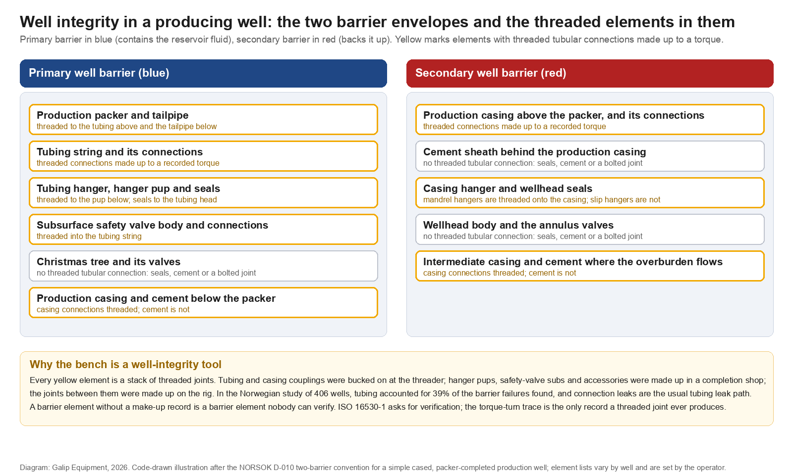
The organising idea is redundancy. Between any source of inflow and the surface there must be two independent well barriers, a primary barrier in direct contact with the pressure and a secondary barrier outside it, so that if the first fails the second contains the well while the problem is found and fixed. The two must not share an element; a leak in a shared element would defeat both at once. Each barrier is a set of well barrier elements, physical components that together form the envelope, and NORSOK D-010 draws them as schematics with the primary envelope in blue and the secondary in red (Offshore Norge, NORSOK D-010 revision 4 overview).
For a simple cased, packer-completed production well the primary barrier is the production packer, the tubing string, the tubing hanger and its seals, the subsurface safety valve and the tree, together with the production casing and cement below the packer. The secondary barrier is the production casing above the packer, the cement behind it, the casing hanger and wellhead seals, and the wellhead body and its annulus valves. Real wells add elements, liners, liner hangers, intermediate strings and their cement, and the operator’s schematic for each well is the authority; the diagram above is the general shape.
Read that list for threads and it is striking how much of the primary barrier is threaded steel. The tubing string is nothing but connections, one every ten metres. The hanger is threaded to a pup, the safety valve to the string, the packer to its tailpipe, and every accessory to the joints around it; the page on well completion explained walks through them. The production casing in both barriers is connections too. Cement, seals and bolted flanges make up the rest, and each has its own verification: a cement bond log, a pressure test, a bolting record. The threaded elements’ verification is the subject of the rest of this page.
What actually fails
Integrity failures are not rare, and the data on what fails is clearer than most people expect. The best-known study examined 406 wells on twelve Norwegian offshore facilities and found that 75 of them, 18 percent, had barrier problems; of the failures identified, tubing accounted for 39 percent and cement for 11 percent, with casing, wellhead, packers and valves making up the rest (Vignes and Aadnøy, SPE 112535, Well-Integrity Issues Offshore Norway). In the US Gulf of Mexico, a review for the federal regulator reported sustained casing pressure, pressure in an annulus that returns after being bled off, on more than 11,000 casing strings in more than 8,000 wells, and noted that the most serious problems had come from tubing leaks (BSEE Technical Assessment Program, A Review of Sustained Casing Pressure Occurring on the OCS). A 2025 review of practice worldwide cites a figure of roughly 7 percent of wells with some form of integrity failure across datasets covering more than 380,000 wells (Journal of Petroleum Exploration and Production Technology, Global regulations and practices for well integrity management).
Two things follow from those numbers. The first is that the threaded element at the centre of the primary barrier, the tubing, is the element that fails most often, and a tubing leak is almost always a connection leak: the pipe body is sound and the joint is not. The second is that the industry’s response, codified in API RP 90 for annular casing pressure management, is a diagnostic discipline: monitor the annuli, bleed and watch the pressure return, work out which element is leaking, and manage the well within limits until it can be fixed (API RP 90, Annular Casing Pressure Management for Offshore Wells). That diagnosis always ends at a question the integrity engineer cannot answer from surface: was this connection made up correctly in the first place?
Qualified connection, unverified make-up
Connections are qualified before they are ever run. ISO 13679 and API RP 5C5 set out the test programme, with connection application levels from CAL I to CAL IV, the highest of which cycles a connection through combined tension, compression, internal and external pressure and bending and requires it to keep sealing throughout (ISO 13679:2019, Procedures for testing casing and tubing connections). A premium connection qualified to CAL IV is a gas-tight barrier element by test. But the qualification tested a connection made up correctly, to the specified torque, with the specified compound, with its sealing faces engaged. Every connection in the well is assumed to match that test specimen, and the only evidence that any particular one does is its make-up record.
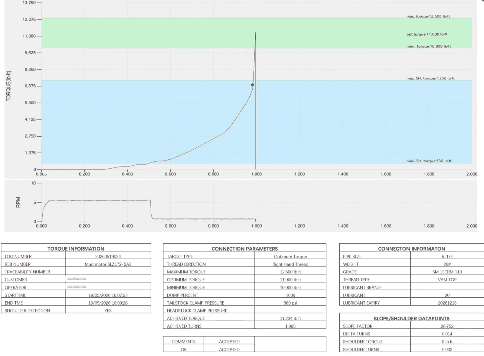
The record is the torque-turn trace: torque against turns from stab to final, with the shoulder point where the sealing faces meet, the final torque inside the connection owner’s window, and the turns past shoulder consistent with the connection’s design. Two joints can reach the same final torque with completely different traces, one with a clean shoulder and one with no inflection at all because the threads galled on the way in; the second will pass a final-torque check and fail in service. How that trace is read, and what a system has to capture, is set out in torque-turn monitoring systems, and the ways a connection leaks after it has passed a pressure test are collected in causes of pipe connection leaks after pressure testing. The quality checks between the mill and the rig that protect the connection before it is made up are a separate subject, covered in OCTG connection integrity after the mill; this page is about the well, and about where the make-up sits in its barrier evidence.
The record a threaded barrier element leaves behind
Each threaded element in the barrier schematic was made up in one of three places, and the integrity file should hold a record from each.
| Barrier element | Where its connections were made up | The record the integrity file should hold |
|---|---|---|
| Casing and tubing couplings | At the mill or threading shop, on a horizontal bench, one coupling per joint | Torque-turn trace per coupling, tagged to the heat and joint number, with the sensor calibration certificate behind it |
| Joint-to-joint connections of casing and tubing | On the rig floor, by the drilling or tubular running crew, as the string was run | The rig’s torque-turn record per joint with accept or reject against the connection owner’s criteria, handed over with the string |
| Tubing hanger pup, safety-valve subs, packer tailpipe, mandrels, nipples, crossovers | In a completion or tool service shop, on a bench, before dispatch | Trace per connection tagged to the accessory serial number, filed with the completion as-built |
| Casing hanger (mandrel type) and the last casing joint | On the rig floor at the end of the run | Part of the rig’s casing record; the hanger’s own thread is a casing connection |
| Wellhead flanges, tree, annulus valves | On location, by the wellhead crew, bolted | Bolting record per joint; a different kind of evidence for a different kind of joint, described in the wellhead in oil and gas |
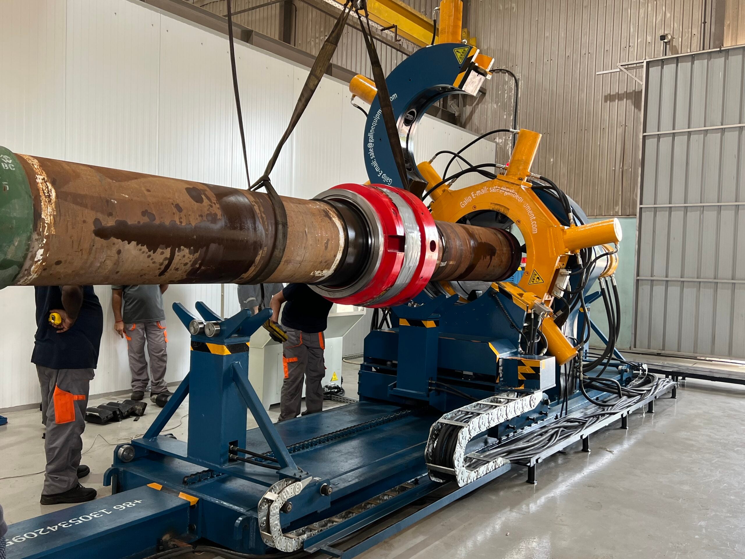
The middle rows are where the bench enters well integrity. The couplings on every joint of tubing and the connections on every accessory in the completion were made up in a workshop, on a horizontal hydraulic bucking unit, often by a company two steps removed from the operator who will one day have to prove the barrier was sound. If that shop kept a trace per connection, tagged and calibrated, the operator’s integrity system has what ISO 16530-1 asks for: verification of the element and documentation of it. If the shop kept a final torque in a logbook, or nothing, the element was never verified and the first annulus pressure reading will start an investigation with no evidence to read.
The record also has to survive. A completion is pulled and re-run at every workover, and the accessories are redressed and made up again in a shop, as the page on workover rig operations follows; each re-make is a new barrier element with a new record. The file ends only at abandonment, when the last barriers are set and the integrity of the well becomes the integrity of its plugs, the subject of plug and abandonment. A make-up record from a bench in a threading shop can therefore be asked for twenty years after it was made, by someone who has never heard of the shop.
What that asks of the bench
A shop that wants its make-ups to count as barrier verification needs four things from its machine, and none of them is torque capacity. It needs the trace itself, recorded at a resolution that shows the shoulder, with the connection parameters, the compound and the operator attached. It needs the record tied to the joint, by heat and joint number for couplings and by serial number for accessories, in a format the operator’s system can file. It needs a calibration chain, so that the torque figures on the trace are traceable to a reference, as set out in torque and load calibration. And it needs the trace exported, as a report the customer can keep, which is what the torque-turn monitoring software on a Galip bench produces for every make-up. The record shown above is one such report, with the customer fields removed.
What the bench cannot do is decide the window. Torque values, turns past shoulder and acceptance criteria belong to the connection owner, and a shop applies them. A record that shows the make-up landed inside the owner’s window is evidence; a record that shows a shop’s own idea of a good torque is a liability.
When another page is the better start
An integrity engineer building a well’s barrier schematic or a well integrity management system is working to ISO 16530-1, NORSOK D-010 and the operator’s own performance standards, and nothing on this site adds to those documents. A reader whose question is the quality chain for pipe between the mill and the rig should start with the OCTG connection integrity page. A shop whose question is what machine and software produce a record that an operator will accept should go to the bucking unit product page and the torque-turn software page, and ask about report formats and calibration. And anyone diagnosing an annulus pressure problem today should be in API RP 90 and the operator’s procedures; this page explains why the diagnosis so often ends at a connection, and what should have been recorded when that connection was made.
The usual limit applies. Barrier definitions, acceptance criteria and torque windows belong to the standards, the operator and the connection owner. This page describes where the evidence comes from; it does not set any of the values.
Frequently asked questions
What is well integrity?
The application of technical, operational and organisational measures to reduce the risk of an uncontrolled release of formation fluids throughout the life of a well, as NORSOK D-010 defines it. ISO 16530-1 sets out how an operator governs it across design, construction, operation, intervention and abandonment through a well integrity management system.
What is a well barrier?
An envelope of one or more well barrier elements that together prevent fluid from flowing uncontrolled within or out of the well. The rule is two independent barriers between any source of inflow and the surface, a primary barrier in contact with the pressure and a secondary barrier outside it, with no element shared between them.
What is a well barrier element?
A physical component that forms part of a barrier envelope: casing, cement, the production packer, the tubing string, the tubing hanger and seals, the subsurface safety valve, the wellhead and the tree. Each element has to be specified, installed, verified and monitored. Threaded elements are verified by the make-up record of their connections.
What is a well integrity management system?
The operator’s system for managing well integrity over the life of its well stock, required by ISO 16530-1. It covers risk assessment, organisation and competence, well barriers and their performance standards, barrier verification, and reporting and documentation. Make-up records from shops and rigs are part of the verification and documentation it relies on.
What is sustained casing pressure?
Pressure in a casing annulus that returns after being bled off, indicating a leak path from a pressured zone or a tubing leak into the annulus. API RP 90 sets out how to monitor, diagnose and manage it. It has been reported on more than 11,000 casing strings in more than 8,000 Gulf of Mexico wells, and the most serious cases have come from tubing leaks.
What does a make-up record have to do with well integrity?
A threaded barrier element is only as good as the make-up of its connections, and the torque-turn trace is the only evidence of that assembly. Tubing is the element that fails most often, and tubing leaks are usually connection leaks. A shop that keeps a trace per connection, tagged and calibrated, gives the operator the verification its integrity system requires.
Send the record format with the enquiry
A shop that supplies operators with integrity-critical tubulars is quoted from what its customers will ask it to prove. The useful set for a bucking unit quotation is: the tubing and casing sizes and connection families run, which connections are premium and need shoulder detection, the record format the operator or its integrity system requires per joint, whether traces must be exported or archived with heat and serial numbers, the calibration interval and certificate the customer expects, the make-up and break-out torque range, the site power supply and a sketch of the bay. The Galip team quotes from that list and will say which report fields match a typical operator’s integrity file.
The well integrity checklist
- Know the two barriers for the wells you supply, and which elements in each are threaded; the operator’s schematic is the authority.
- Treat every make-up on a threaded barrier element as a verification event, with a torque-turn trace, not a final torque.
- Tag each trace to the joint: heat and joint number for couplings, serial number for accessories.
- Apply the connection owner’s window and acceptance criteria; never a shop’s own figures.
- Keep the calibration certificate behind every trace, and renew it on the interval the customer specifies.
- Export and archive the record so it can be found twenty years later by someone who has never heard of the shop.
- Expect the record to be re-made at every workover and to end only at abandonment.
- When a customer reports annulus pressure, be the supplier who can produce the trace for the joint in question.
Expert Consultation
Need more information on optimizing your equipment performance? Our engineering team is available for technical consultations.
Request a Quote
Tell us about your requirements and our engineering team will prepare a detailed proposal with specifications, pricing, and delivery timeline.
