
Liner Hanger in Oil and Gas: What a Liner Is, How the Hanger Sets, and What Goes Wrong
A liner is a casing string hung inside the bottom of the casing above it instead of running back to surface. The liner hanger grips that casing with slips, a packer seals the top of the lap, and the whole assembly is made up, pinned and tested at the service base before it goes to…
A liner hanger in oil and gas wells is the tool that hangs a liner, a casing string that does not reach surface, from inside the casing above it. Slips on the hanger bite into that casing and carry the liner’s weight; a liner top packer then seals the overlap. The hanger is run on drill pipe, set by pressure or rotation, and left in the well.
At a glance
| What a liner is | A string of ordinary casing joints hung inside the bottom of the previous casing, overlapping it, instead of running back to the wellhead |
| What the hanger does | Grips the casing above with slips on a cone and carries the liner’s weight; most systems add a packer that seals the top of the overlap |
| How it sets | Mechanically by rotation and set-down weight, hydraulically by a dropped ball and pump pressure, or by expanding the hanger body |
| Why operators use liners | Less steel, a lighter string to run, a larger bore above the liner top, and the option to tie back to surface later |
| The main risks | A leak at the lap, a hanger that sets early, a running tool that will not release, and a narrow annulus that is hard to cement |
| Equipment standard | API Specification 19LH for liner hanger equipment; liner top packers are often also validated to ISO 14310 / API 11D1 |
| Decision this page supports | Choosing between a liner and a full string, and deciding what the base must make up, pin and test before the hanger assembly ships |
What is a liner in a well?
In an oil or gas well, a liner is a casing string that starts downhole instead of at the wellhead. Its joints are the same casing joints used in any other string; the difference is that its top hangs inside the bottom few hundred feet of the previous casing, and the two overlap (SLB Energy Glossary: liner). Water-well “liners” are something else, usually plastic pipe slid inside an old well casing, and nothing on this page applies to them.
A liner does the same work as the string it replaces. A drilling liner cases off a trouble zone so the next section can be drilled with a different mud weight; a production liner runs across the reservoir and is perforated, or is run as slotted pipe or screens without cement. Where liners sit in the full casing program, from conductor to production casing, is set out in casing strings explained.
What a liner hanger does
The slips on a liner hanger, wedge-shaped steel segments with hardened teeth, ride up a cone on the hanger body and bite into the casing wall, and the liner’s weight drives them tighter. Once the hanger has taken that weight, the running tool on the drill pipe unlatches and can be picked up. The liner top packer, set after cementing, then closes the annulus at the top of the lap so nothing can migrate up behind the liner.
SLB dates its own liner hanger line to 1952, when MWL Tool Company developed a liner hanger in Midland, Texas. Since then load and pressure ratings have gone up, rotating hangers let the liner turn while it is cemented, and expandable hangers have dropped the slips altogether.
Liner vs casing: hang a liner or run a full string?
An operator choosing between a liner and a full string to surface is trading cost and hydraulics against one more potential leak path.
| Factor | Effect to consider | Points toward |
|---|---|---|
| Steel and rig time | A liner needs only the bottom section of pipe and is run on drill pipe, so the string is lighter and cheaper | Liner, when the rig’s hook load or the pipe cost is the limit |
| Bore above the liner top | The larger casing stays open above the lap, which lowers circulating friction and leaves room for larger tubing. In one Permian case, the operator moved to a liner design so it could run 4 in. tubing instead of 2-7/8 in. | Liner, when the completion needs a bigger bore in the upper well |
| Later options | A receptacle at the liner top lets a tieback string be run to surface later if the upper casing wears or a higher pressure rating is needed | Liner with a tieback receptacle, when the well’s life may change |
| The lap | The overlap is an extra seal point, and its narrow annulus is harder to cement than open hole | Full string, when a single continuous barrier to surface is worth the cost |
| Downhole tools | The hanger, packer and running tool each add a way for the job to go wrong | Full string, on simple shallow wells where the savings are small |
Types of liners
- Drilling (intermediate) liner. Isolates a lost-circulation, salt or pressure-transition zone so drilling can continue.
- Production liner. Runs across the reservoir. Usually cemented and perforated; in open-hole completions it may be slotted pipe or screens run without cement.
- Tieback liner. Run from the top of an existing liner back to the wellhead and stabbed into the receptacle at the liner top, often to raise the pressure rating for a frac or to cover worn casing.
- Scab liner. A short string across damaged or corroded casing, sealed or cemented at both ends, that neither hangs at the bottom nor reaches surface.
- Drill-in liner. Rotated or reamed to bottom through a difficult hole, which needs a hanger and running tool rated for the torque.
Inside the liner hanger assembly
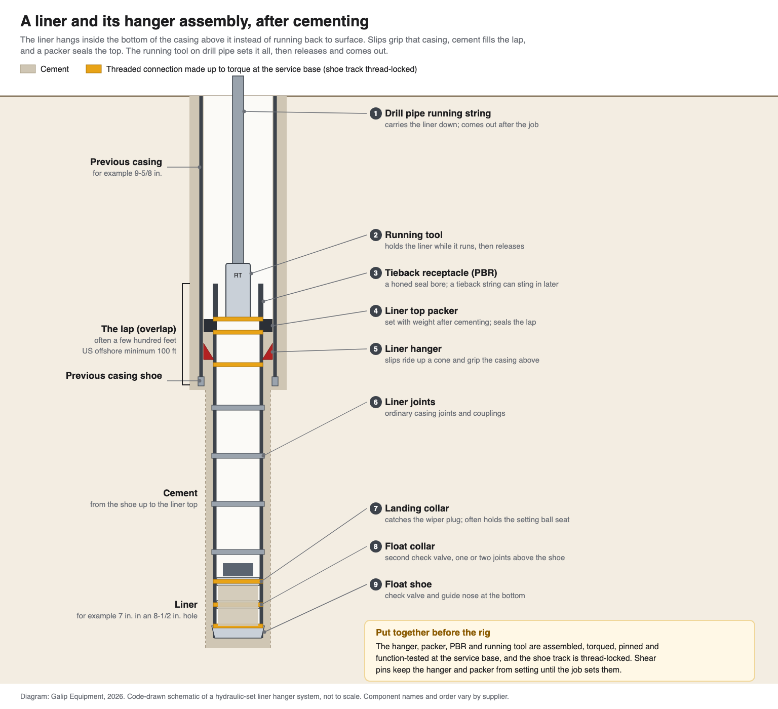
A cemented liner on a hydraulic hanger is built like this, from the drill pipe down; the numbers match the diagram above, and suppliers use different names for some parts:
- Drill pipe running string. Carries the liner down and comes out after the job. At the end of the cement job a drill pipe dart is pumped down it behind the cement.
- Running tool. On the bottom of the drill pipe; carries the liner, transmits weight and, on rotating systems, torque, then releases. The liner wiper plug hangs below it on shear pins; the dart latches into the plug, shears it free, and the pair travel down to the landing collar.
- Tieback receptacle (PBR). A polished, honed seal bore at the very top. The running tool’s packoff seals in it during the job; a tieback string or production seal assembly can sting into it later.
- Liner top packer. A sealing element with hold-down slips, set with weight after cementing.
- Liner hanger. Slips and cone, held unset by shear pins until the job sets them.
- Liner joints. Ordinary casing, with centralizers.
- Landing collar. Catches the liner wiper plug at the end of the cement job and often carries the seat for the setting ball. The landing collar, float collar and shoe together form the shoe track, covered in well cementing and float equipment.
- Float collar. A second check valve, one or two joints above the shoe.
- Float shoe. A guide nose and check valve on the bottom joint.
The equipment from the hanger up, including packers, receptacles and running tools, is covered by API Specification 19LH, Liner Hanger Equipment, first published in 2019. Its scope stops at the equipment: installation, float equipment and landing collars are outside it. Liner top packers are validated as complete tools, to the grades in API 19LH and often also to ISO 14310 / API 11D1, whose grades run from V6 up to V1, with V0, which allows no gas bubbles, at the top.
Types of liner hangers: mechanical, hydraulic, rotating and expandable
| Type | How it sets | Where it fits |
|---|---|---|
| Mechanical | The running string is rotated, often about a quarter turn to the right through a J-slot, then weight is slacked off to push the slips up the cone | Shallower, straighter wells where rotation and weight reach the hanger reliably |
| Hydraulic | A ball is dropped onto a seat below the hanger; pump pressure shears pins and strokes a piston that drives the slips up the cone | Deviated and deep wells, where downhole rotation and weight are uncertain |
| Rotating | Mechanical or hydraulic, with bearings so the liner can be turned after the hanger sets | Long or high-angle liners where rotating during cementing improves mud removal |
| Expandable | The running tool expands a section of the hanger body against the casing; bands on the body grip and seal at once, with no slips, cones or cylinders | Wells where fewer leak paths and no risk of early setting justify the cost; harder to retrieve once set |
A rotating liner loses much of the surface torque before it reaches the liner. In one NOV case on a 9-5/8 in. liner in Norway, 50,000 ft-lb applied at surface delivered only about 29,000 ft-lb at the liner top, and the liner did not start turning until roughly 33,500 ft-lb reached it. The connections near the top of the liner carry most of that torque, so each connection is made up to its full specified value before the job, and that value must exceed the torque expected while rotating.
Running, setting and cementing a liner, step by step
A typical sequence for a hydraulic-set, cemented liner with a liner top packer:
- Check the assembly delivered from the base: drift the drill pipe and tools so the ball and dart will pass, and confirm the shear pin values against the job design.
- Run the shoe track and liner joints, filling the liner and confirming the floats work.
- Pick up the hanger assembly, made up and tested at the base with the running tool in place, and make it up to the top liner joint, with tongs only on the marked tong areas and no rotation of the running tool against the hanger.
- Run in on drill pipe, recording up and down weights. Keep any circulating pressure at or below about 80% of the hanger’s setting pressure so it cannot set early.
- At depth, circulate and condition the mud, reciprocating or rotating if the system allows.
- Drop the ball and pressure up to shear the pins and set the slips, slack off to confirm the hanger has taken the weight, then raise the pressure to shear out the ball seat and re-establish circulation.
- Release the running tool and pick up a short distance to prove it is free, keeping the packoff in the seal bore.
- Pump spacer and cement, rotating or reciprocating where possible.
- Launch the drill pipe dart; it latches the liner wiper plug and shears it free.
- Bump the plug on the landing collar, then bleed off and check that the floats hold.
- Pick up, set down weight to set the liner top packer, and circulate excess cement off the liner top.
- Pull out of the hole, wait on cement, and test the liner top.
For the completion that later goes inside the liner and ties into its top, see well completion explained.
The lap and the liner-top test
The overlap between the liner and the casing above, the lap, has to be long enough to hold cement and a seal. US offshore rules set the floor: an intermediate or production liner’s top must be at least 100 ft above the previous casing shoe, and a liner used as surface casing at least 200 ft (30 CFR 250.421). Field practice varies, and laps of 50 to 200 ft are still run to save cost. A BSEE-funded study published in 2019 recommended at least 300 ft of overlap, a 300 to 500 ft cement column across gas zones, and a 90-minute pressure test for laps of 300 ft or more.
Once the cement has set, the lap is tested from both sides. A positive test pressures the casing from above to prove the packer, hanger seals and lap cement hold. A negative test lowers the pressure above the liner top, for example by displacing to a lighter fluid, and watches for inflow, which proves the lap holds against formation pressure from below, the direction that causes kicks. US offshore rules require a production liner and its top to be tested to at least 500 psi above the fracture pressure at the shoe it laps into, treat a pressure drop of more than 10% in 30 minutes as a failure, and require a negative test on the final string in wells with a subsea BOP or a mudline suspension system (30 CFR 250.721). The lap is one part of the well’s barrier envelopes; well integrity and barriers shows where it fits.
What goes wrong with liner hangers
| Failure | Typical cause | What prevents it |
|---|---|---|
| Hanger or packer sets early | Circulating or surge pressure near the shear value, debris, or drag on the setting sleeve | Pump limits below the setting pressure, verified pin values, controlled running speed |
| Liner will not reach depth | Ledges, doglegs, losses or differential sticking | Hole conditioning; a hanger and running tool rated to rotate or ream the liner down |
| Hanger will not set or slips will not hold | Wrong casing weight for the cone, damaged slips, ball not seated, pins not as tagged | Casing weight checked against the hanger, pins counted at the base and on the rig |
| Running tool will not release | Too much weight on the tool, or cuttings packed around it | Correct neutral point, clean returns, and a planned contingency release |
| Running tool releases too early | Torque in the release direction during running or reciprocation | Knowing which hand the tool releases with and keeping torque the other way |
| Lap leak | Poor cement in the narrow lap, a damaged element, or a packer not fully set | Rotation during cementing, a properly set packer, and positive and negative tests |
| Shoe track backs off during drill-out | Connections not thread-locked; the bit’s right-hand rotation drags the shoe-track parts to the right, which unscrews them from the casing above | Shoe track thread-locked and made up to torque before the job |
Before the rig: the work at the service base
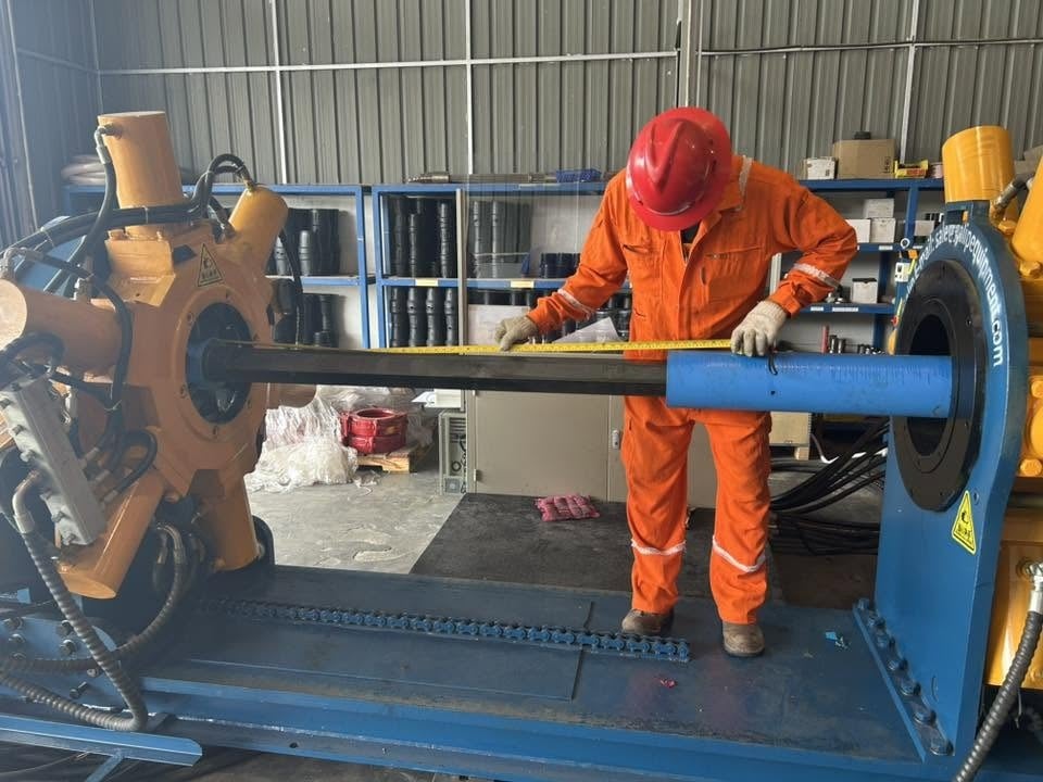
Much of a liner hanger job is prepared before the assembly reaches the rig. Liner running procedures recommend that the hanger system, with its running tool, pup joints, plug holder and packer extension, be made up as an assembly and tested at the contractor’s workshop. There it is drifted, measured and tallied, its shear pins are counted against the job design, and it is pressure- and function-tested. Field checklists add that the service hand should count the pins personally rather than trust a tag, and that the shoe track must be thread-locked so drilling out the shoe cannot unscrew it.
The threaded connections in the assembly, between the running tool’s setting sleeve, the receptacle, the packer, the hanger and the first liner pup, are made up to the torque on each supplier’s sheet, and many of them are premium connections accepted on a torque-turn graph. At a service base this is done on a make-up machine such as a Galip hydraulic bucking unit, which clamps the two bodies, applies and holds the torque, and records each joint’s graph for the job file. The grips go on the bodies, clear of the slips, the cone and the polished seal bore, and nothing is turned in the release direction of the running tool. How to read the graphs is covered in torque-turn graph interpretation, and the layout of a bench at a completion tool base in the completion tool make-break cell.
When a full string is the better choice
A liner is not always worth its savings. These cases usually go the other way:
- Shallow, simple wells. The steel saved is small, and the hanger, packer and running tool add cost and risk the saving does not cover.
- Wells where the lap would sit across a problem. If the overlap would have to sit in worn or corroded casing, or across a zone that makes good cement unlikely, a continuous string avoids the weak point.
- Wells that will be tied back anyway. If a tieback to surface is certain from day one, running the full string in one trip can be simpler than a liner plus a tieback.
- A base without the means to prepare the assembly. Where no one can make up, pin and pressure-test a hanger assembly properly, the job should be bought complete from a supplier who can, with the records.
Frequently asked questions
What is the difference between a liner and casing?
A liner is casing that does not reach surface. Its joints are ordinary casing joints, but its top hangs inside the bottom of the previous casing on a liner hanger, overlapping it, instead of running up to the wellhead. A full casing string is landed on a hanger in the wellhead at surface.
What is a liner hanger used for?
A liner hanger suspends a liner from the inside of the casing above it. Slips on the hanger grip the casing and carry the liner’s weight so the running string can release and come out. Most hangers are run with a liner top packer that seals the overlap once the liner is cemented.
What is a tubing hanger used for, and how is it different from a liner hanger?
A tubing hanger carries the weight of the production tubing at the wellhead and seals the tubing from the annulus; it sits in the tubing head at surface. A liner hanger sits downhole and hangs a liner from the inside of the previous casing, gripping it with slips. One holds tubing at surface; the other holds casing deep in the well.
How does a hydraulic liner hanger set?
A ball is dropped down the drill pipe and lands on a seat below the hanger. Pump pressure then builds behind it until shear pins break and a piston drives the slips up the cone and into the casing wall. The crew slacks off weight to confirm the hanger is carrying the liner, then raises the pressure to shear out the ball seat so cement can be pumped.
What is a liner top packer?
A liner top packer is a sealing element with hold-down slips at the top of the liner, above the hanger. It is set with weight after the liner is cemented and closes the annulus between the liner and the casing above, so gas or fluid cannot migrate up through the lap.
How much overlap does a liner need?
US offshore rules require the top of an intermediate or production liner to be at least 100 ft above the previous casing shoe, and 200 ft for a liner used as surface casing. In practice laps are commonly around 300 ft, longer in deep high-pressure or gas wells.
What is a tieback liner and a PBR?
A PBR, or polished bore receptacle, is a honed seal bore at the top of the liner. A tieback liner is a casing string run later from the wellhead down to the liner top, where seals on its bottom sting into the PBR. It is used to raise the pressure rating or cover worn casing above.
Why is a liner rotated during cementing?
Turning the liner while cement is pumped breaks up gelled mud on the low side of the annulus so cement can replace it, which gives a better seal in the narrow lap. It needs a rotating hanger, a running tool rated for the torque, and every connection in the liner made up to its full specified torque.
Before running a liner: the checklist
- The liner length, the lap length and the liner top depth are set in the program, with the lap meeting the regulator’s minimum.
- The hanger is matched to the weight and grade of the casing it will grip, and its load rating covers the buoyed liner weight plus the packer setting force.
- Shear pin values for the hanger, packer, ball seat and wiper plug are listed, and the pins were counted at the base.
- Every connection from the running tool to the first liner pup was made up to its specified torque at the base, with a torque-turn record for premium connections.
- The shoe track was made up and thread-locked before the job, and the floats were function-checked.
- The assembly was pressure- and function-tested and its measured lengths are on the tally.
- The drill pipe, crossovers and tools are drifted so the setting ball and dart will pass.
- Maximum circulating pressure while running is written down, at or below about 80% of the hanger setting pressure.
- The release direction of the running tool and its contingency release are known to everyone on the floor.
- The positive and negative liner-top tests are planned, with their pressures and hold times written down.
Expert Consultation
Need more information on optimizing your equipment performance? Our engineering team is available for technical consultations.
Request a Quote
Tell us about your requirements and our engineering team will prepare a detailed proposal with specifications, pricing, and delivery timeline.
