
Casing Strings in Oil and Gas: The Types, Their Sizes, and How Each One Is Run
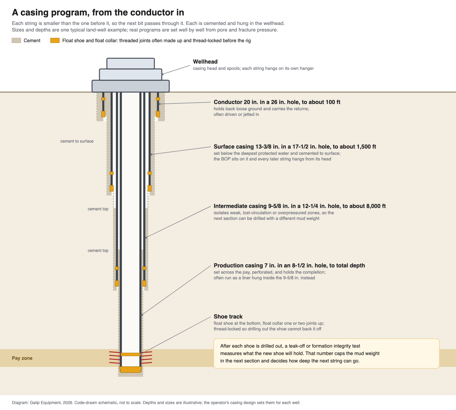
A well is lined with several casing strings, each smaller than the one before and each cemented in place: conductor, surface, intermediate and production casing, or a liner hung from the string above. Pressure decides where each one stops; the next bit decides its size.
Casing strings are steel pipe joints screwed together, run into a drilled oil or gas well and cemented in place to hold the hole open and seal off each rock layer. A well usually has several: conductor, surface, intermediate and production casing, or a liner. Each is smaller than the one before so the next bit fits through, and each stops where the mud weight has to change.
At a glance
| What a string is | Joints of casing, most about 40 ft long, joined by threaded couplings, run to a set depth and cemented |
| The usual strings | Conductor, surface, intermediate (none, one or several) and production casing; a liner is a string hung from the one above instead of reaching surface |
| What sets the depth | The window between formation pore pressure and fracture pressure, the depth of protected groundwater, and trouble zones |
| What sets the size | The bit for the next section has to pass the drift of the casing above it, with room around the couplings for cement |
| The governing standards | API Specification 5CT for the pipe, API 5B for API threads, API TR 5C3 for strength formulas; premium connections follow the licensor’s own procedure |
| The threaded part | Every joint and coupling, plus the float shoe, float collar, pups and crossovers, many of them made up before the pipe reaches the rig |
| Decision this page supports | Reviewing a casing program’s shoe depths and sizes, and deciding which threads are made up and recorded before the pipe reaches the rig |
What is a casing string?
A casing string is the steel lining of a well. Joints of casing pipe, usually around 40 ft (12 m) each, are threaded on both ends and joined by short double-box couplings, run into the hole one after another, and then cemented to the rock (SLB Energy Glossary: casing string). Once the cement sets, the string holds the hole open, keeps fluids in each layer where they belong, and gives the next section a pressure-tight base to drill from.
Casing is ordered by a short line that carries most of what matters. Take 9-5/8 in. 47 lb/ft P-110 BTC Range 3. The outside diameter is 9-5/8 in. The weight per foot sets the wall, here 0.472 in., for an inside diameter of 8.681 in. and a drift of 8.525 in., the minimum bore a gauge must pass. P-110 is the steel grade, and the number is the minimum yield strength in thousands of psi: 110,000 psi. BTC is buttress thread and coupling, one of the API thread forms. Range 3 is the length class. Pipe like this is part of the family known as oil country tubular goods, or OCTG.
The weight also decides which bit fits. The same 9-5/8 in. pipe at 53.5 lb/ft has an 8.535 in. inside diameter and a standard drift of 8.379 in., too small for an 8-1/2 in. bit, which is why programs that need the heavier wall order it with an alternate 8.500 in. drift. How drift is checked is covered in the casing and tubing drift test.
Why a well needs more than one string
A hole can only be drilled with one mud weight at a time. The mud has to be heavy enough to hold back the fluid in the most pressured open formation, and light enough not to fracture the weakest one. That gap between pore pressure and fracture pressure is the drilling window. Deeper, the window shifts; when the mud weight the next zone needs would break down a zone already open above, that open hole has to be cased off before drilling on.
Casing programs are therefore designed from the bottom up. The engineer starts with the size the completion needs at the reservoir, then walks up the pressure profile and puts a shoe wherever the window runs out. After each string is cemented and its shoe drilled out, a leak-off or formation integrity test measures what the new shoe will hold, and that number caps the mud weight for the next section. US offshore rules set a default margin: the equivalent downhole mud weight must stay at least 0.5 lb/gal below the lower of the shoe test and the lowest estimated fracture gradient, unless BSEE approves a different margin justified in the drilling permit (30 CFR 250.414).
Two other things move shoe depths: groundwater, which surface casing has to cover by law, and trouble zones such as salt, swelling shale or lost-circulation intervals, which are often cased off as soon as they have been drilled.
Types of casing strings, from the outside in
Names vary by region, but the strings below cover almost every well. The sizes and depths are typical; each well’s program sets its own.
| String | What it does | Typical size and depth |
|---|---|---|
| Structural or drive pipe | Supports soft seabed or surface soil before anything else; mainly offshore | Driven, jetted or drilled to a shallow depth |
| Conductor | Holds back loose ground, carries the returns back to the pits, and gives a base for a diverter | 16 to 30 in., commonly 20 in. on land; tens to a few hundred feet |
| Surface casing | Covers fresh-water zones, is cemented to surface, carries the BOP and supports every later string through the wellhead | 13-3/8 in. is common on land; a few hundred to about 2,000 ft, set by the groundwater depth |
| Intermediate casing | Isolates weak, lost-circulation, salt or overpressured zones so the next section can use a different mud weight | 9-5/8 or 10-3/4 in. is common; depth set by the pressure profile |
| Production casing | Runs across or into the reservoir, is perforated, and holds the completion | 4-1/2, 5-1/2 or 7 in. are common |
| Liner | A string hung inside the bottom of the previous casing on a liner hanger, not run back to surface; saves steel | Any of the deeper sizes; overlaps the string above by a few hundred feet |
| Tieback | Extends a liner back to surface later, by stabbing into the receptacle at the liner top | Same size as the liner |
A real program shows how much these depths move. In a Delaware Basin saltwater disposal well presented at a 2017 AADE symposium, the standard design set 20 in. casing at 300 ft, 13-3/8 in. at 2,000 ft, 9-5/8 in. at 9,000 ft and 7 in. at 14,000 ft. To cut injection friction, the big-hole design set the 20 in. at 2,000 ft and the 13-3/8 in. at 11,500 ft, and ran 9-5/8 in. as a liner to 14,000 ft with a tieback (AADE, “A Big Dig in West Texas”). Every shoe moved, and the well ended one casing size larger at the bottom.
Conductor casing vs surface casing
The two are often confused because both are shallow and large. They do different jobs, and different people decide their depth.
| Point | Conductor | Surface casing |
|---|---|---|
| Main job | Keeps loose ground from caving and gives the mud a return path while the surface hole is drilled | Seals off fresh-water zones and gives the well its first pressure-rated base |
| What sets its depth | Soil and engineering; deep enough to reach competent ground | The deepest protected water, set by the regulator |
| How it goes in | Often driven or jetted, or drilled and cemented | Drilled, run with a shoe track and cemented to surface |
| What sits on it | A diverter, if anything | The casing head, the BOP stack, and every later string through the wellhead |
The groundwater rule is what makes surface casing a regulatory string. In Texas, surface casing must cover usable-quality water, which the Railroad Commission’s Groundwater Advisory Unit defines as generally 3,000 mg/L dissolved solids or less, to a depth the unit sets for each location. The operator must cement surface casing from the shoe back to the ground surface, centralize it at the shoe and on every fourth joint, and wait for the critical cement to reach 500 psi before drilling out (16 TAC §3.13). The federal 10,000 mg/L line for an underground source of drinking water (40 CFR 144.3) mainly applies to injection and disposal wells. Offshore, US rules cement the conductor back to the mudline and require surface casing cement at least 200 ft up inside the conductor (30 CFR 250.421).
Why casing sizes step down
Each string has to pass through the one above it, and the bit that drills its hole has to pass first. That sets the familiar pairs: a 26 in. hole for 20 in. casing, 17-1/2 in. for 13-3/8 in., 12-1/4 in. for 9-5/8 in., and 8-1/2 in. for 7 in. The hole is larger than the casing because the couplings stand proud of the pipe body and the cement needs room around them to fill the annulus evenly.
The sizes are not free choices. The production casing is fixed by the tubing, pumps and completion tools the well needs; every string above it is then the next size that leaves room for its bit and its cement. A program that adds an unplanned string loses a size at the bottom, which is one reason liners and slim connections exist.
Reading a casing order: grade, connection and range
Grade. API Specification 5CT covers casing and tubing; its 11th edition was published in December 2023, with an addendum in 2025 that stresses casing and tubing as well barriers (API announcement). The 11th edition covers H40, J55, K55, N80, R95, L80, C90, T95, C110, P110 and Q125, and the 2025 addendum adds C125; what the letters mean is set out in API 5CT grades and connections. L80 Type 1, C90, T95 and C110 are the restricted-yield grades for sour service; P110 is common in deep, high-pressure strings where sour service is not a concern. Grade M65 was dropped from the specification in the 10th edition.
Range. API length classes for casing are Range 1 (16 to 25 ft), Range 2 (25 to 34 ft) and Range 3 (34 to 48 ft). Rigs prefer Range 3, roughly 40 ft, because fewer joints mean fewer connections to make up. Anything shorter than Range 1 is a pup joint, used to space out the string so a coupling or hanger lands at the right depth; see pup joints, crossovers and casing accessories.
Connection. API connections, short and long round thread (STC, LTC) and buttress (BTC), are threaded and gauged to API Specification 5B. They seal on thread compound in the thread clearances, and a buttress joint is judged by position: the coupling face should stop between the base and the apex of a triangle stamped on the pin. Buttress thread connections covers that in detail. Most premium connections add a metal-to-metal seal and a torque shoulder, and are accepted on a torque-turn graph that shows the shoulder; wedge-thread designs have no shoulder and use the licensor’s own graph criteria. Many licensors and operators call for a graph on every joint.
How casing is run and cemented
On the rig, a casing crew picks up each joint, stabs it into the coupling of the string below, and makes it up with power tongs or with a casing running tool driven by the top drive. Thread compound goes on before each make-up. On premium strings, every connection is monitored and its torque-turn graph saved; on API strings, position and torque are checked against the maker’s table. The string is filled as it goes in, unless float equipment is set up to fill itself. The full crew and equipment side is in tubular running services.
The bottom of the string is the shoe track; well cementing and float equipment follows it from the plugs to the drill-out. A float shoe guides the pipe past ledges and carries a check valve; a float collar with a second check valve sits one or two joints above it. Cement is pumped down behind a bottom plug, a top plug follows it, and the top plug lands on the float collar, leaving a short column of cement inside the shoe track so the shoe itself is surrounded by good cement. Centralizers keep the pipe off the low side so the cement fills all the way round.
The string’s weight goes onto a casing hanger in the wellhead: a mandrel hanger is landed before the cement job, and slips are set after it. The annulus is then sealed off above the hanger, and the casing is pressure-tested, often when the top plug bumps and always before the shoe is drilled out. Each string’s hanger stacks inside the casing head or a spool; the wellhead in oil and gas shows the order.
The threads made up before the rig
Not every connection in a casing string is made on the rig floor. Two sets are commonly made up earlier, in a mill or a shop.
The coupling on every joint. Each joint leaves the threading line with a coupling already made up on one end, the mill end, so the rig only makes up the other, the field end. Coupling makers call this step mill-end make-up, or bucking (Hunting coupling make-up procedure). For its TKC semi-premium connections, Hunting’s mill-end procedure requires at least the minimum published torque, checks coupling ovality at the open end, drifts the made-up joint, and asks for a torque-turn graph for every connection when torque-turn monitoring is used. How a threading shop runs that step is described in casing coupling make-up in the threading shop.
The shoe track and accessories. The float shoe, the float collar, and often the joints between them are made up before the job, frequently with thread-locking compound instead of welding, so the drill-out cannot unscrew them. Forum Energy Technologies sells its thread-locking compound for that purpose (Forum Energy Technologies: BAKERLOK) and notes that welding shoes and collars to casing often weakens the casing. Pups, crossovers and hanger joints are prepared the same way when the program calls for them.
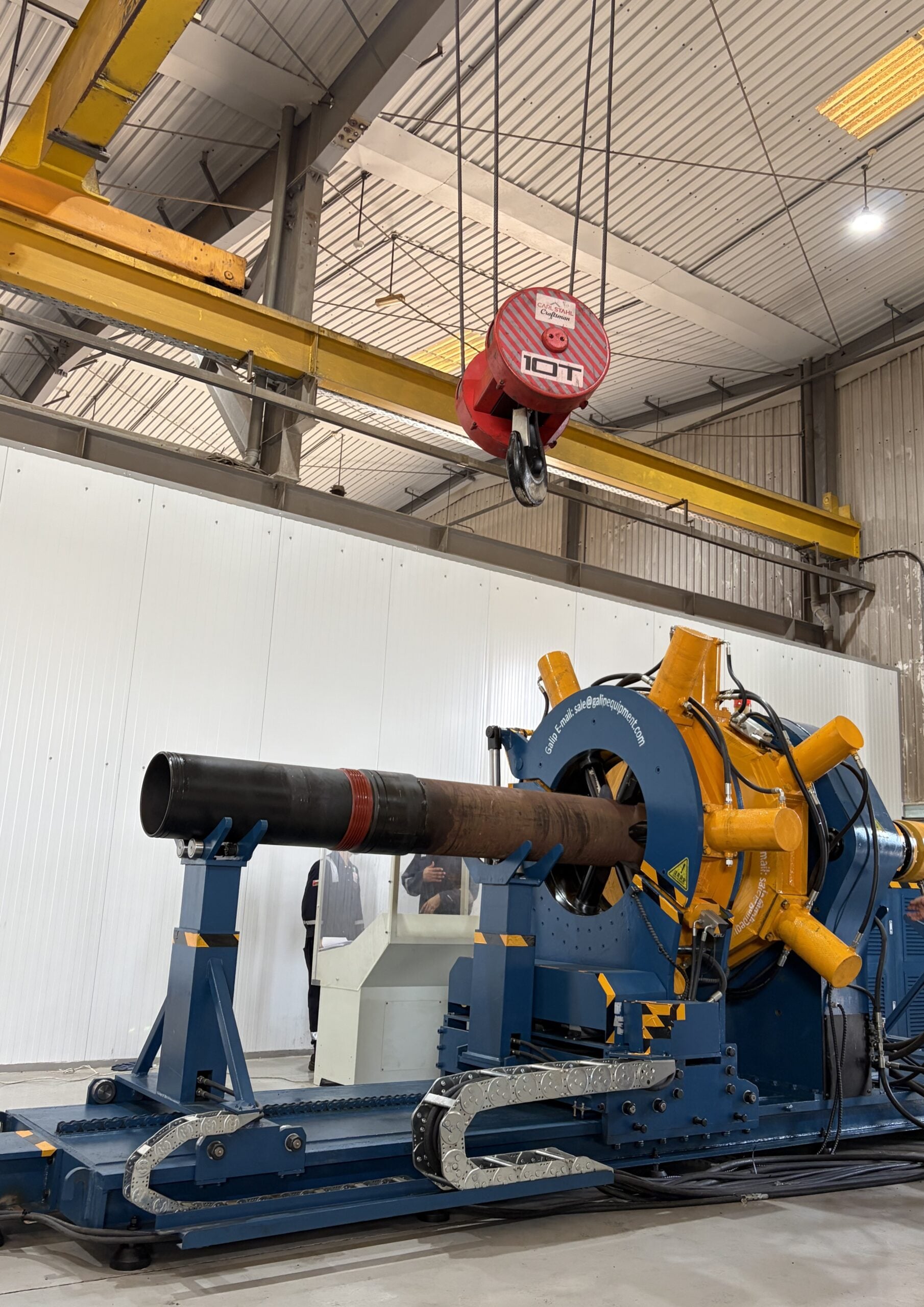
Both jobs can be done on a horizontal machine that clamps the pipe body and the coupling or accessory and turns one against the other to a set torque; shoe tracks are also often made up on location with the rig’s tongs. A Galip hydraulic bucking unit does this in threading shops and service bases, and records the torque and turns of each joint so the record ships with the pipe. Whether the joint is made on a shop machine or by a tong on the rig, the acceptance rules are the same: the connection maker’s torque values, position against the triangle for API buttress, and on shouldered premium threads a graph with a visible shoulder.
Casing design: burst, collapse and tension
Once sizes and shoe depths are fixed, each string is checked against three loads. Burst is internal pressure greater than the pressure outside, worst during a kick or a pressure test. Collapse is outside pressure greater than inside, worst when the casing is emptied or across mobile salt. Tension is the hanging weight of the string plus the pull to free it if it sticks, worst at the top. The strength formulas are in API TR 5C3, published with ISO/TR 10400, and the weight and grade are chosen so that each rating divided by its load stays above a design factor.
Operators set their own design factors. Values commonly quoted are around 1.1 for burst, 1.125 for collapse and 1.6 to 1.8 for tension, but these are examples, not legal minimums; US offshore rules require the program to state the factors used, not to use particular ones (30 CFR 250.415). This is also why one string can have several weights or grades: heavier wall at the bottom for pressure, stronger steel near the top for the hanging weight.
Where a shop machine does not fit
A make-up machine handles only some of the threads in a casing string. It plays no part in these:
- The rig-floor connections. The great majority of joints in a string are made up on the rig by tongs or a casing running tool, monitored there; a shop machine never sees them.
- Large-bore conductor and surface pipe with weld-on or wedge connectors. Many 20 in. and larger strings use connectors that are welded on at a plant and stabbed together at the rig, not made up to a torque in a shop.
- Operators buying ready-made accessories. If the float equipment, pups and crossovers arrive from a supplier already made up, the step that matters is checking that supplier’s make-up records, not owning a machine.
- Casing damage downhole. Wear, corrosion or a leak in a cemented string is a well intervention problem: a patch, a scab liner, a tieback or a cement squeeze.
Frequently asked questions
What does casing mean in oil and gas?
In oil and gas, casing is large-diameter steel pipe that lines a drilled well and is cemented in place. Joints about 40 ft long are screwed together into casing strings that hold the hole open, keep fluids in each rock layer from moving into others, protect groundwater and give the next section a pressure-tight base.
What are the different types of casing in a well?
From the outside in: structural or drive pipe offshore, the conductor, surface casing, one or more intermediate strings, and production casing. A liner is a string hung inside the bottom of the previous casing instead of reaching surface, and a tieback can later extend a liner back to the wellhead.
What is the difference between conductor casing and surface casing?
The conductor is the first, shallowest and largest string; it keeps loose ground from caving and carries the mud returns while the surface hole is drilled. Surface casing goes deeper, below the protected groundwater, is cemented to surface, and carries the casing head and the BOP stack for the rest of the well.
What is Range 3 casing?
Range 3 is an API 5CT length class for casing joints between 34 and 48 ft long, typically about 40 ft. Range 1 is 16 to 25 ft and Range 2 is 25 to 34 ft. Rigs prefer Range 3 because fewer, longer joints mean fewer connections to make up; pup joints are shorter than Range 1.
What is the difference between casing and tubing?
Casing lines the hole and is cemented in place for the life of the well. Tubing is the smaller string run inside the production casing that carries the produced fluid to surface. Tubing is not cemented, hangs in the tubing head, and can be pulled and replaced during a workover.
How deep is surface casing set?
Surface casing must reach below the deepest groundwater the regulator protects, so the depth changes with location; in Texas it comes from a Groundwater Advisory Unit letter for each well. On land it is commonly a few hundred to about 2,000 ft, and it may go deeper where the shallow geology needs it.
Can you replace the casing in an oil well?
Cemented casing is not normally pulled out and replaced. Damaged or leaking casing is repaired in place with a casing patch, a scab liner across the damage, a tieback string, or a cement squeeze. If repair is not practical, the well is plugged. Water wells are a different case and can sometimes be relined.
How long does casing last in an oil or gas well?
There is no fixed lifespan. Casing life depends on corrosion from produced fluids, the loads it sees, and the quality of the cement around it. Operators watch for sustained pressure in the annulus between strings, one of the first signs that a barrier is no longer holding, and repair or plug the well when it appears. Water-well casing is a different case.
Before running casing: the checklist
- Each shoe depth sits where the drilling window runs out, and the reason for each one is written in the program.
- Surface casing reaches below the deepest protected water named by the regulator, with its cementing and wait-on-cement rules noted.
- Every string is listed with size, weight, grade, connection and range, and the drift has been checked against the next bit size.
- Burst, collapse and tension design factors are stated for each string, with the load case that governs each.
- Pipe was inspected and drifted on arrival, thread protectors stayed on until the pipe was racked, and the mill-end couplings were checked.
- The float shoe, float collar, pups and crossovers were made up to their torque before the job, thread-locked where specified, and the records came with them.
- Thread compound, make-up torque values and, for premium connections, torque-turn acceptance criteria are on the rig floor before the first joint is picked up.
- Centralizer placement, the cement volumes and the plug sequence match the program.
- The casing hanger, its seal assembly and the landing joint are measured and spaced out with pup joints where needed.
- The casing pressure test and the shoe leak-off test after drill-out are scheduled, with their test pressures written down.
Expert Consultation
Need more information on optimizing your equipment performance? Our engineering team is available for technical consultations.
Request a Quote
Tell us about your requirements and our engineering team will prepare a detailed proposal with specifications, pricing, and delivery timeline.
