
Bottom Hole Assembly Design: Build, Hold and Drop BHAs
Bottom hole assembly design explained: compare build, hold and drop BHAs, check stabilizer gauge, place drilling jars and record every connection.
\n
Bottom hole assembly design starts with the bit and ends at the top of the heavy weight drill pipe. This lower section of the drill string provides weight on bit, controls directional behaviour, and carries the tools needed for the run. The bit is specified on its own terms, and what a tricone bit’s IADC code encodes is the shorthand every supplier quotes against. It may include drill collars, stabilizers, a mud motor, a drilling jar, a shock sub, and survey tools. Their order affects how the assembly bends, where the bit points, and how much weight reaches the bottom. The SLB Energy Glossary definition of a bottomhole assembly lists the same core hardware and functions. The full string above it, component by component, is in drill string components.
\n\n\n\n
Article contents
\n\n\n\n
Bottom hole assembly design at a glance
\n\n\n\n
| Question | Short answer |
|---|---|
| Where does it start and end? | At the bit, up to the top of the heavy weight drill pipe |
| What is it for? | Weight on bit, hole direction, and everything measured downhole |
| What controls direction? | Where the stabilizers sit relative to the bit |
| Three classic types | Build, hold and drop |
| Same parts in all three? | Mostly yes. Placement is what differs |
| Biggest field variable | Stabilizer gauge. An undergauge stabilizer changes the behaviour |
\n\n\n\n
Bottom hole assembly components, from the bit upward
\n\n\n\n
The order is not decorative. Each component sits where it does because of what it needs to be near.
\n\n\n\n
| Component | Job | Why it sits there |
|---|---|---|
| Bit | Cuts the rock | Bottom, by definition |
| Near-bit stabilizer | Centralises the string just above the bit | Its distance from the bit sets the directional tendency |
| Mud motor, if run | Turns the bit independently of string rotation | The bit makes up into the motor’s bit box, so a motor run has no separate near-bit sub. The near-bit stabilizer becomes a sleeve on the bearing housing, and the survey package sits above the motor |
| Survey tools | Measure inclination and azimuth | Inside non-magnetic collars, away from steel |
| Drill collars | Weight on bit, in compression | Low, so the neutral point stays inside them |
| Jar | Delivers an impact if the string sticks | In the tension section above the neutral point and deliberately clear of it, since a jar sitting at the neutral point can fire on its own |
| Heavy weight drill pipe | Stiffness step between collars and pipe | Above the collars, below the pipe |
\n\n\n\n
A vertical hole in soft rock might use collars and one or two stabilizers. A directional well carries a motor, a measurement package, several stabilizers and a jar, and the order they go in gets argued over before the string goes in the hole.
\n\n\n\n
Build, hold and drop bottom hole assembly designs
\n\n\n\n
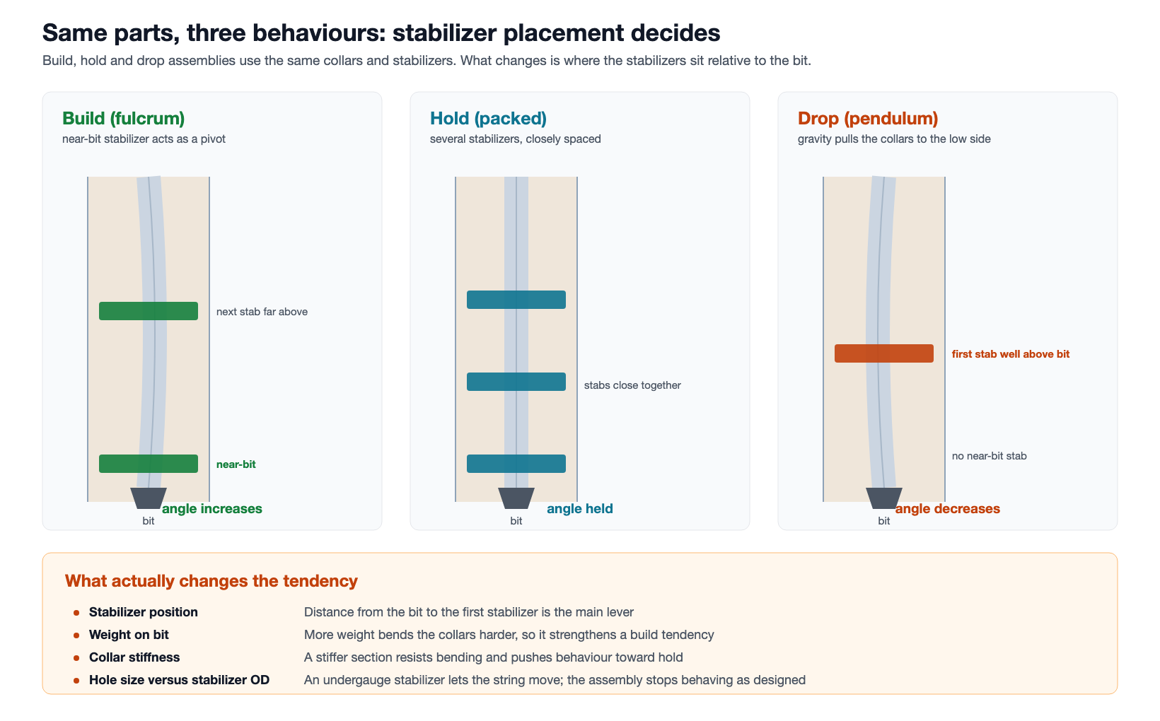
Build, hold, and drop are the three classic bottom hole assembly design families used for rotary assemblies. Most use similar components. Stabilizer placement is what changes the directional tendency.
\n\n\n\n
\n\n\n\n
| Configuration | Arrangement | Effect on hole angle |
|---|---|---|
| Build, also called fulcrum | Stabilizer right at the bit, then a long gap before the next one | Increases angle |
| Hold, also called packed | Three or more stabilizers, closely spaced, the first at the bit | Holds the angle it has |
| Drop, also called pendulum | No near-bit stabilizer; first one well above the bit | Reduces angle |
\n\n\n\n
In a build assembly the near-bit stabilizer becomes a pivot. Weight on bit bends the unsupported collars above it, the bit tilts toward the high side, and the hole angle climbs. Add weight and the effect strengthens, which is why a directional driller adjusts weight to steer a rotary assembly.
\n\n\n\n
A drop assembly does the opposite by leaving out the near-bit stabilizer. The collar section between the bit and the first stabilizer hangs unsupported, gravity pulls it to the low side of the hole, and that sideways force tilts the bit downward.
\n\n\n\n
Weight works the other way here, and this catches people out. A pendulum only drops at low weight on bit. Push too hard and the collars between the bit and the first stabilizer buckle onto the low side: the effective pendulum shortens, the side force collapses, the bit tilts back up and the assembly stops dropping. If a pendulum will not drop, weight is the first thing to come off.
\n\n\n\n
A hold assembly takes the freedom to bend away. Three or more stabilizers, the first of them at the bit, leave the string too little room to flex. Note what that does and does not mean: it holds the inclination and azimuth the hole already has, and it does not continue a trend. Run it into a section that was building two degrees per thirty metres and the build stops.
\n\n\n\n
Why stabilizer gauge changes BHA behaviour
\n\n\n\n
Every one of those mechanisms assumes the stabilizers touch the hole wall. A stabilizer 1/8 in under gauge on diameter lets the string sit 1/16 in off centre, half the diameter deficit, and that is enough to soften a build tendency measurably. The loss is progressive, not a switch, which is why the reading on the ring gauge matters more than a pass or fail feel.
\n\n\n\n
This is a common reason a directional plan and the actual survey disagree. The assembly was correct on paper and the stabilizers came out of the rack undergauge. Check gauge with a ring gauge before the string goes in, and reject against the number in your inspection specification or the operator’s drilling programme, written on the sheet before the job starts. A rack that is short is not a reason to accept an out-of-gauge blade.
\n\n\n\n
| Symptom | What it usually means | What to check |
|---|---|---|
| Build assembly is not building | Near-bit stabilizer undergauge, or weight on bit too low | Stabilizer gauge first, then the weight actually reaching the bit |
| Hold assembly drifting | Stabilizer spacing too wide, or one is undergauge | Measure all of them, not just the near-bit |
| Drop assembly not dropping | Weight on bit too high, so the collars are buckled onto the low side and the pendulum is lost. Less often a tight hole | Reduce weight and watch the next survey before touching anything else |
| Angle changing when nothing changed | Formation dip, or a stabilizer wearing during the run | Offset well behaviour in the same formation |
\n\n\n\n
Where to place a drilling jar in the BHA
\n\n\n\n
Most drilling jars are double-acting: they fire up on an overpull and down on set-down weight. The up-blow governs placement, because that is the one you want available when the string sticks, so the jar belongs where the string carries tension. Put it too low, buried in the collars, and it sits in compression where an overpull cannot reach it properly.
\n\n\n\n
The usual placement is near the top of the collars or within the heavy weight, so it stays in tension while drilling. The mass above the jar is also what delivers the blow, so a jar set with too little weight above it fires weakly even from the right zone. Both have to be satisfied at once, which is why placement is calculated: enough buoyed weight above the tool to reach its rated up-trip load with the overpull the rig can actually apply, and that trip-load figure comes off the jar’s data sheet.
\n\n\n\n
What belongs on the BHA tally
\n\n\n\n
Every assembly that goes in the hole is recorded on a tally. It is the document a fishing company reads at three in the morning, so it earns the effort.
\n\n\n\n
| Recorded | Why it is needed later |
|---|---|
| Every item in order, with serial numbers | Identifies what is downhole if the string parts |
| Length of each item to two decimal places | Puts a depth on anything left in the hole |
| Maximum OD of each item | Decides whether a fishing tool can pass it |
| Minimum ID, and any restriction | Decides what can be dropped or pumped through |
| Connection at each end of every item | A mixed rack carries mixed connections; a fishing string has to match one |
| Stabilizer gauge as measured, with the date | Explains directional behaviour that did not match the plan |
| Make-up torque applied, per connection | Separates a back-off from a twist-off after the event |
\n\n\n\n
The two entries most often left blank are stabilizer gauge and applied torque, and they are the two that answer the questions asked after something goes wrong. A gauge figure written the morning the string went in settles an argument about whether the assembly could ever have built angle. A torque figure per connection settles whether a joint came apart because it was under-torqued or because it fatigued.
\n\n\n\n
A recorded torque value must come from equipment that can capture and store the applied torque. A tong gauge gives the operator a reading, but it does not create a retrievable connection record. That is the practical difference between reading torque and documenting it.
\n\n\n\n
Keep the sheet with the tools rather than in a folder on the rig. When the same assembly comes back to a workshop three months later, the gauge figures and torques on it are the only record of how it was run.
\n\n\n\n
When bottom hole assembly design is not the cause
\n\n\n\n
| Problem | More likely cause | Look here first |
|---|---|---|
| Slow penetration rate | Bit selection or hydraulics | Bit record and flow at the bit |
| Weight will not reach the bit | Drag in a deviated hole | Pick-up and slack-off weights |
| Survey readings suspect | Magnetic interference from steel too close | Non-magnetic spacing around the survey tool |
| Connection failures in the collars | Cyclic bending fatigue, not the configuration | Dogleg exposure and the inspection interval |
| Stuck pipe | Differential sticking or hole cleaning | Overbalance and contact area |
\n\n\n\n
Of those five, drag and hole cleaning are the two most often mistaken for a directional problem, because both first show up as an assembly that will not do what it did on the last run.
\n\n\n\n
What the workshop sees between BHA runs
\n\n\n\n
Between runs, the BHA comes apart in the workshop. The technician does not see a neat diagram. The bench receives a rack of short, heavy parts, often with plain surfaces that are difficult to grip.
\n\n\n\n
- \n
- Collars and stabilizers are short and heavy, with plain bodies that offer little for pipe slips to grip.
- Connections have been in compression and rotation, so they open harder than they closed.
- Stabilizer blades are the part that gets measured. Undergauge blades are usually a rebuild: welded up, re-dressed to gauge and re-hardfaced, or a new sleeve on the replaceable-sleeve designs. Body or connection damage is what condemns one.
- Motors, jars and survey subs each go to a different bay with different acceptance criteria.
\n
\n
\n
\n
\n\n\n\n
The practical consequence for anyone equipping that shop is that the OD range on an enquiry has to cover the largest item in the assembly, and the break-out torque has to cover connections that were made up hard and then worked. What a service centre needs to handle a mixed rack is set out in the downhole tool service centre guide.
\n\n\n\n
Bottom hole assembly design checklist
\n\n\n\n
- \n
- Required weight on bit, and enough buoyed collar weight in the mud actually being run to supply it. Plan on using no more than about 80 to 85 per cent of that buoyed weight so the neutral point stays inside the collars at maximum weight on bit
- Directional intent for the section: build, hold or drop, with the target rate of change
- Stabilizer positions measured from the bit and written on the BHA sheet. Do not carry them over from the last run
- Stabilizer gauge verified against a ring gauge before the string goes in
- Non-magnetic length around the survey tool, calculated for the hole’s inclination and azimuth and for the geomagnetic field where the well sits. High magnetic latitude and east-west azimuths both need more than a low-latitude hole heading north
- Jar position in the tension zone, with enough mass above it to make the blow useful
- Connection designations recorded for every item, since a mixed rack carries mixed connections
- Fishing plan: what would go around each component if the string parted at it
\n
\n
\n
\n
\n
\n
\n
\n
\n\n\n\n
The last item is the one people skip. Every component OD in the assembly is a decision about whether a fishing tool can pass it later, taken months before anyone needs the answer. The fishing tools themselves, and the service centres that keep them, are described in downhole tools.
\n\n\n\n
Bottom hole assembly design FAQ
\n\n\n\n
What is a bottom hole assembly?
\n\n\n
A bottom hole assembly (BHA) is the lower end of the drill string, from the bit up to the top of the heavy weight drill pipe. A BHA normally includes drill collars, stabilizers, and any motor, jar or survey equipment the run requires.
\n\n\n\n
What are the components of a bottom hole assembly?
\n\n\n
Bit, near-bit stabilizer, a mud motor if one is run, survey tools inside non-magnetic collars, drill collars, a jar, and heavy weight drill pipe at the top. A vertical hole may use only collars and one or two stabilizers.
\n\n\n\n
What is the difference between a build and a drop assembly?
\n\n\n
A build assembly has a stabilizer immediately above the bit acting as a pivot, so weight on bit tilts the bit upward and the angle increases. A drop assembly leaves that stabilizer out, so the collars hang to the low side and the angle falls.
\n\n\n\n
How does weight on bit affect direction?
\n\n\n
In a build assembly, more weight bends the collars harder against the near-bit pivot and strengthens the build. In a packed hold assembly the effect is small, because the string has little room to bend.
\n\n\n\n
Why do stabilizers have to be in gauge?
\n\n\n
Because they only control the string while they touch the hole wall. A stabilizer under gauge leaves clearance for the string to move, and the assembly behaves like a different design from the one that was planned.
\n\n\n\n
Where should a drilling jar sit?
\n\n\n
In the tension section, usually near the top of the collars or in the heavy weight, with enough mass above it to deliver a useful impact. Buried low in the collars it sits in compression and an overpull cannot work it properly.
\n\n\n\n
Do you still need stabilizers and collars when running a mud motor?
\n\n\n
It changes how steering is done rather than removing the need for the rest. A motor with a bent housing steers by orienting the bend, but the collars, stabilizers and survey package around it still have to be sized and placed.
\n\n\n\n
Where does heavy weight drill pipe go in a BHA?
\n\n\n
Directly above the drill collars and below the drill pipe, filling the transition zone so bending stiffness changes in steps. In a BHA the heavy weight also gives the jar somewhere to sit in tension. The stiffness-step arithmetic is on the drill collar sizing page.
\n\n\n\n
Specifying workshop equipment for BHA work
\n\n\n\n
For workshop make-up and breakout work, three specifications matter most:
\n\n\n\n
- \n
- OD range covering the largest item in the rack, usually a stabilizer or a collar, not the pipe
- Break-out capacity comfortably above the highest make-up torque in the rack, checked against the largest connection you handle rather than the average, since these connections come back harder than they went together
- How plain, blade-covered and coated bodies will be gripped, and the marking limit your customers accept on each
\n
\n
\n
\n\n\n\n
Those three shape the machine more than the headline torque figure does. The specification side sits on the make-up and break-out equipment page.
\n\n\n\n
7 essential bottom hole assembly design checks
\n\n\n\n
- \n
- A BHA runs from the bit to the top of the heavy weight drill pipe
- Build, hold and drop use the same parts in different positions
- Distance from the bit to the first stabilizer is the main directional lever
- Weight on bit strengthens a build tendency and does little in a packed assembly
- An undergauge stabilizer turns the design into a different one
- Jars belong in tension, with mass above them
- Fishing tool clearance is set by the largest OD in the string, not the smallest
\n
\n
\n
\n
\n
\n
\n
\n\n
Expert Consultation
Need more information on optimizing your equipment performance? Our engineering team is available for technical consultations.
Request a Quote
Tell us about your requirements and our engineering team will prepare a detailed proposal with specifications, pricing, and delivery timeline.
