
Drill Collar: Weight on Bit, Slick vs Spiral and Sizing
A drill collar supplies weight on bit in compression so the pipe above stays in tension. How to size the collar string, and when spiral beats slick.
A drill collar is a thick-walled steel tube run directly above the bit to supply weight on bit in compression. How much weight the bit can accept is a bit specification rather than a string one, and it is one of the numbers the IADC bit classification deliberately leaves out. Drill pipe cannot do that job. Put drill pipe in compression and it buckles and fatigues, so the string is arranged with enough collar weight below to keep everything above it in tension.
At a glance
| Question | Short answer |
|---|---|
| What is it for? | Weight on bit, and stiffness near the bit |
| Why not use drill pipe? | Pipe in compression buckles and fatigues; collars are built for it |
| What is the neutral point? | Where axial load changes from compression to tension. It must sit inside the collars |
| How much weight do you need? | Required weight on bit, divided by buoyancy factor, times a design margin |
| Slick or spiral? | Spiral cuts wall contact to resist differential sticking, at a small weight cost |
| What connections? | Usually NC or REG, machined into the body rather than welded on |
Why the neutral point governs the design
Push down on a long slender tube and it bows sideways. That is drill pipe in compression, and every bow is a bending cycle that accumulates fatigue in a component already turning at speed. A drill collar has a far thicker wall and a much higher stiffness, so it takes compression without buckling. How collars, heavy-weight pipe and drill pipe divide that job is set out in drill string components.
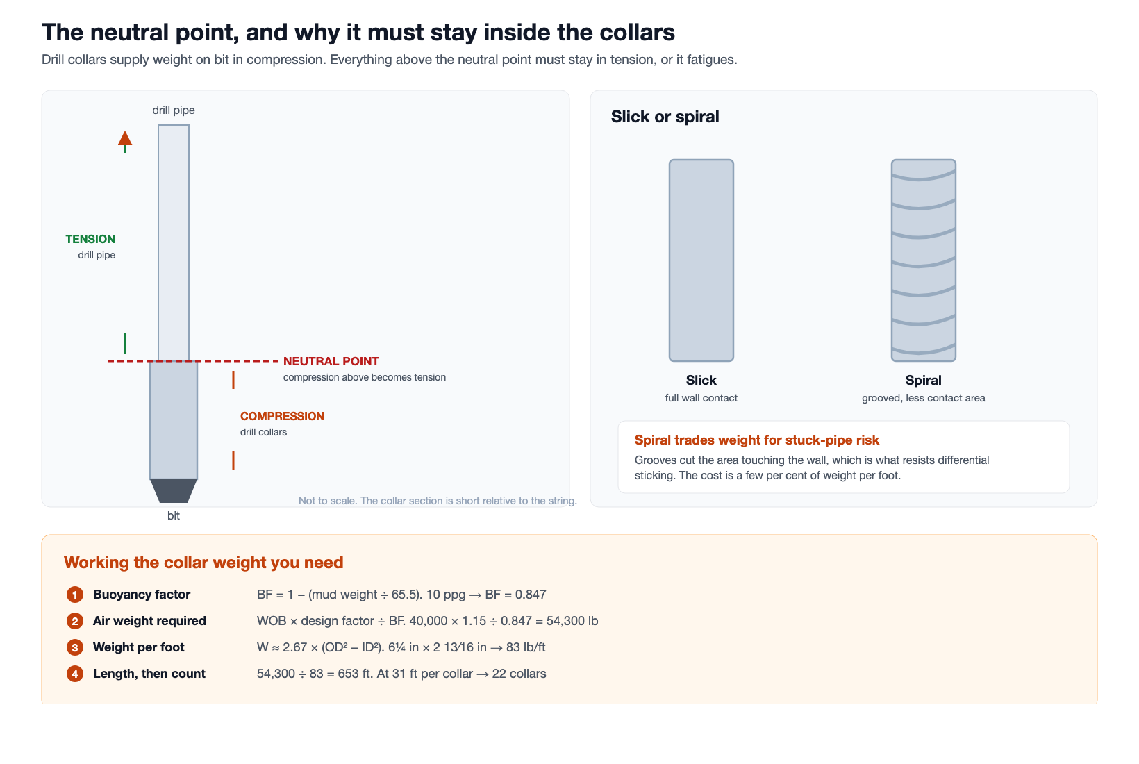
Somewhere in the string there is a point where axial load passes through zero and compression becomes tension. That is the neutral point, and the whole sizing exercise exists to keep it below the top of the collar section with margin to spare. If it climbs into the drill pipe, the pipe is being asked to do a job it was not built for.
Two things move it. Adding weight on bit pushes it up the string. Adding collar weight pushes it back down. Since weight on bit changes constantly as the bit works, the design carries a margin rather than sitting exactly on the boundary.
Working out how much collar weight you need
The arithmetic is short and worth doing rather than inheriting from the last well.
Buoyancy factor   BF = 1 − (mud weight in ppg ÷ 65.5)
Air weight needed = weight on bit × design factor ÷ BF
Weight per foot   W ≈ 2.67 × (OD² − ID²)   in lb/ft, inches
Length            = air weight needed ÷ weight per foot
Take 40,000 lb of weight on bit in a vertical hole with 10 lb/gal mud, and a design factor of 1.15 so the neutral point stays clear of the pipe.
| Step | Working | Result |
|---|---|---|
| Buoyancy factor | 1 − (10 ÷ 65.5) | 0.847 |
| Air weight needed | 40,000 × 1.15 ÷ 0.847 | 54,300 lb |
| Weight per foot, 6¼ in × 2 13⁄16 in | 2.67 × (6.25² − 2.8125²) | 83 lb/ft |
| Length required | 54,300 ÷ 83 | 653 ft |
| Number of collars at 31 ft | 653 ÷ 31 | 21.1, so 22 |
Two details change the answer. In a deviated hole only the component of weight along the hole axis presses on the bit, so the requirement rises with inclination. And the design factor is a judgement, not a constant: a hole with severe doglegs or unpredictable weight transfer deserves more than 15 per cent.
Buoyancy is the step most often skipped. Working in air weight alone under-sizes the string, because a collar hanging in 10 lb/gal mud contributes only about 85 per cent of its air weight.
One habit worth building into the collar count: order the string with a joint or two of margin rather than exactly the calculated number. Collars come out of service for connection work, and a rack that is exactly sized means the first rejected joint changes the drilling parameters rather than just the maintenance schedule.
Sizing the collar OD to the hole
Collar outside diameter is not a free choice. It is squeezed between two opposing requirements, and both are worth stating plainly.
| Pushing OD up | Pushing OD down |
|---|---|
| More weight per foot, so a shorter collar string | Annular clearance for cuttings and for circulating pressure |
| More stiffness, which helps hold hole angle | Fishing: a larger collar in a given hole is harder to get an overshot around |
| Less contact stress against the wall for the same weight | Differential sticking risk rises with contact area |
The fishing consideration is the one crews remember, because it only matters on the day something goes wrong. If a drill collar OD leaves too little clearance in the hole, the tools that would normally recover it may not pass. That is a design decision taken months earlier by whoever picked the collar size.
Bore matters as much as OD and gets less attention. It sets weight per foot through the same formula, and it sets the pressure drop through the collar section. A heavier collar with a smaller bore buys weight at the cost of circulating pressure, which is a real trade when a mud motor downstream needs its own share of the pressure budget.
Slick, spiral and square
| Type | What it is | When it is chosen |
|---|---|---|
| Slick | Plain cylindrical body | The default. Maximum weight per foot for a given size |
| Spiral | Helical grooves machined into the body | Where differential sticking is a risk, at a small cost in weight |
| Square | Squared cross-section | Stiffness and hole control in specific directional work |
Spiral collars are the interesting choice. Differential sticking happens when a collar rests against a permeable formation and mud pressure pins it there, and the force holding it is proportional to the contact area. Cutting helical grooves removes a large share of that contact area while giving up only a few per cent of weight per foot. In a hole with high overbalance and permeable sands, that trade is usually worth taking.
It is not free. You lose some weight, the grooves collect a little more mechanical damage, and the reduced section is one more thing to inspect. On a hole where sticking is not a live risk, slick collars give more weight for the same footage and the same money.
Connections, and why they are the weak point
A drill collar has no upset and no welded-on connector. The connection is machined directly into the body, which makes it fundamentally different from drill pipe.
That matters because the collar section runs in compression and rotation at the same time, so the connections there see bending fatigue at exactly the point where the section changes. Collar connection failures are common enough that stress relief features and careful make-up torque are standard practice rather than optional. The designation families and what the numbers mean are set out in the guide to rotary shouldered connections and NC designations.
| Practice | Reason |
|---|---|
| Make up to the published torque for the connection and collar OD | Torque is set by the connection and the metal around it, not by the hole size |
| Use stress relief features on larger collars | Softens the load transfer at the last engaged thread, where fatigue starts |
| Break out and inspect on a schedule, not on failure | Collar connections fail from accumulated cycles, so time in service is the signal |
| Keep a bevel and shoulder condition record | The shoulder carries the preload; damage there defeats the torque |
The transition zone: why you cannot go straight to drill pipe
A stiff drill collar sitting directly beneath thin-walled drill pipe creates an abrupt change in bending stiffness. When the string rotates through a dogleg, the bending has to go somewhere, and it concentrates at that step. The connection just above the collars is a common fatigue failure for exactly this reason.
The fix is to step down rather than jump. Stiffness is compared using section modulus, and the ratio between two adjacent components is the number that matters:
Section modulus   Z = π × (OD⁴ − ID⁴) ÷ (32 × OD)
Stiffness ratio   SR = Z of the lower component ÷ Z of the upper component
Common practice keeps that ratio modest, tightening the limit as hole conditions get rougher. A benign vertical hole tolerates a larger step than a hole with severe doglegs, where the accepted figure drops considerably. The principle is more useful than any single number: the bigger the stiffness jump and the worse the doglegs, the harder that connection works.
| Component | Role in the transition | Runs in compression? |
|---|---|---|
| Drill collar | Supplies weight on bit, sets the stiffness at the bottom | Yes, by design |
| Heavy weight drill pipe | Intermediate stiffness between collars and pipe | Yes, within limits, which is what makes it useful |
| Drill pipe | Carries tension and transmits rotation and flow | No |
Heavy weight drill pipe is the usual answer. It has a thicker wall than standard pipe, longer tool joints, and often a wear pad in the middle of the joint. It bridges the stiffness gap, adds some weight, and tolerates limited compression, which is why a modern string frequently carries a section of it between the collars and the pipe rather than stacking on more collars.
There is a practical benefit too. Heavy weight handles like pipe rather than like a drill collar, so replacing part of the collar count with it makes the string quicker and safer to trip.
Handling: short, heavy and awkward
A collar is roughly the same length as a joint of drill pipe and several times the weight, with no upset to grip and a smooth body that offers nothing to a set of slips designed for pipe.
- Safety clamps are used because the plain body gives slips less to work with.
- Lift subs or lifting nubbins screw into the connection to give an elevator something to hold.
- Support spacing matters in the rack, because a short heavy section on too few supports takes a set.
- Break-out torque is high, since these connections were made up hard and then rotated in compression.
The workshop consequence is that collars are gripped differently from pipe. A machine set up for drill pipe body diameters and pipe-weight handling is not automatically right for a rack of collars, and the OD range quoted on an enquiry needs to cover the collar, not the pipe it runs above.
What wears on a drill collar, and where to look
Collars fail differently from pipe. The body is thick and rarely the problem; the ends and the contact surfaces are.
| Area | What happens | Consequence if missed |
|---|---|---|
| Connections | Fatigue cracking at the last engaged thread, galled or dented shoulders | Twist-off or a washout downhole |
| Outside diameter | Abrasive wear, especially on slick collars in hard formation | Reduced stiffness and a looser fit than the design assumed |
| Elevator and slip recesses | Wear and bruising where handling equipment grips | Handling becomes unsafe before anything else fails |
| Bore | Erosion and internal corrosion | Changes weight per foot and weakens the section |
| Spiral grooves | Mechanical damage at the groove edges | Stress raisers in a section already reduced |
The inspection interval is driven by rotating hours and dogleg exposure rather than by the calendar, and the connection is the item that decides it. Because a drill collar connection is cut into the body, there is no separate welded connector to replace: a connection worn past its limit means recutting, and a cracked one means the end comes off.
Grading logic for used drill string components, and how a worst-feature rule works, is set out in what an inspection class actually guarantees. The same principle applies here: one connection below limit condemns the joint whatever the body measures.
When collar weight is not the deciding factor
| Symptom | More likely cause | Check first |
|---|---|---|
| Cannot get weight on bit in a deviated hole | Drag along the hole, not insufficient collar weight | Pick-up and slack-off weights against the drag model |
| Repeated stuck pipe | Differential sticking or hole cleaning | Overbalance and contact area before adding collars |
| Connection failures in the collar section | Fatigue at the last engaged thread from cyclic bending | Dogleg severity and the connection inspection interval |
| Erratic bit performance | Bit selection, hydraulics or vibration | The bit record and the flow before the string design |
| Survey accuracy problems | Magnetic interference, which steel collars cause | How much non-magnetic length a survey needs |
That last row is the one that catches people out. Standard steel collars are magnetic, which is exactly why a directional string carries non-magnetic collars around the survey tool. Sizing steel collars for weight and positioning non-magnetic collars for survey accuracy are two separate calculations that happen to involve the same component family.
Specification checklist
- Outside diameter, chosen against hole size and the stiffness step to what sits above
- Bore, since it sets both weight per foot and flow area
- Length, usually the standard range rather than a special
- Slick, spiral or square, decided on sticking risk rather than habit
- Connection designation, quoted as NC or REG rather than a size and a letter
- Stress relief features, specified or explicitly declined
- Material and whether any part of the string needs to be non-magnetic
- Hardbanding, if the collar will contact casing
Frequently asked questions
What does a drill collar actually do?
It supplies weight on bit in compression and adds stiffness near the bit. It exists so the drill pipe above never has to carry compression.
Why can drill pipe not provide weight on bit?
It is slender and thin walled, so it buckles under compression and accumulates bending fatigue as it rotates. Collars have the wall thickness and stiffness to take that load.
How do I calculate drill collar weight?
Divide the required weight on bit by the buoyancy factor, multiply by a design factor, then divide by the weight per foot of the collar size you intend to run. Weight per foot is approximately 2.67 × (OD² − ID²) in pounds per foot with inches.
What is the difference between slick and spiral drill collars?
Spiral collars have helical grooves that cut the area touching the hole wall, which reduces the risk of differential sticking. They give up a few per cent of weight per foot in exchange.
Where should the neutral point be?
Inside the collar section, with margin. That is what the design factor buys. If it rises into the drill pipe, the pipe is in compression and fatiguing.
Are drill collars magnetic?
Standard steel ones are, which is why directional strings carry non-magnetic collars around the survey instrument. Those are specified for magnetic properties, not for weight.
Why do collar connections fail more often than pipe connections?
They run in compression and rotation at once, and the connection is cut into the body rather than into a separate welded connector. That puts cyclic bending straight into a section change, which is where fatigue starts.
Specifying for a shop that handles collars
If a workshop makes up and breaks out collars rather than only pipe, three things on the enquiry matter more than the rest:
- OD range that covers the largest collar, not the drill pipe body
- Break-out torque with margin, since collar connections open harder than they closed
- How the plain body will be gripped, and the marking limit you accept on it
Where the string also needs non-magnetic sections, those are a different material with different handling and hardness limits. The specifications are on the non-magnetic collar page.
Short checklist
- Collars carry compression so the pipe above does not have to
- The neutral point must stay inside the collar section, with margin
- Buoyancy is part of the sum, not a refinement
- Weight per foot ≈ 2.67 × (OD² − ID²)
- Spiral trades a little weight for a lot less sticking risk
- Connections are cut into the body, so fatigue is the failure mode
- Handling needs safety clamps and lift subs, not pipe habits
Expert Consultation
Need more information on optimizing your equipment performance? Our engineering team is available for technical consultations.
Request a Quote
Tell us about your requirements and our engineering team will prepare a detailed proposal with specifications, pricing, and delivery timeline.
