
Tool Joint: Connection Types, Sizes and Wear Limits
A tool joint is a rotary shouldered connection: the shoulder seals, the threads hold. NC designations and their older names, the dimensions that govern, and wear limits.
A drill pipe tool joint is the heavy threaded connector welded to each end of a joint of pipe: a box at one end, a pin at the other. It is a rotary shouldered connection, which means the seal is made by two machined shoulders pressing together. The threads hold the joint in tension. They do not seal it.
At a glance
| Question | Short answer |
|---|---|
| What is it? | The forged, welded-on connector at each end of a drill pipe joint |
| What seals it? | The shoulder faces, not the threads |
| How is it named? | By connection style, most commonly the NC series |
| What does the NC number mean? | Pitch diameter at the gauge point, in inches, times ten and truncated |
| What decides make-up torque? | Box outside diameter and pin bore, on the tool joint’s own material. Pipe body grade does not enter into it |
| What wears out first? | Box OD, then the shoulder faces |
Pin, box and the shoulder that does the work
Each length of drill pipe carries a pin on one end and a box on the other, so joints stack in one orientation all the way down the string. A tool joint is a different steel from the tube it sits on and is quenched and tempered separately to its own specification, which is why the two are joined by friction welding rather than a fusion weld, and why the weld zone gets its own heat treatment afterwards.
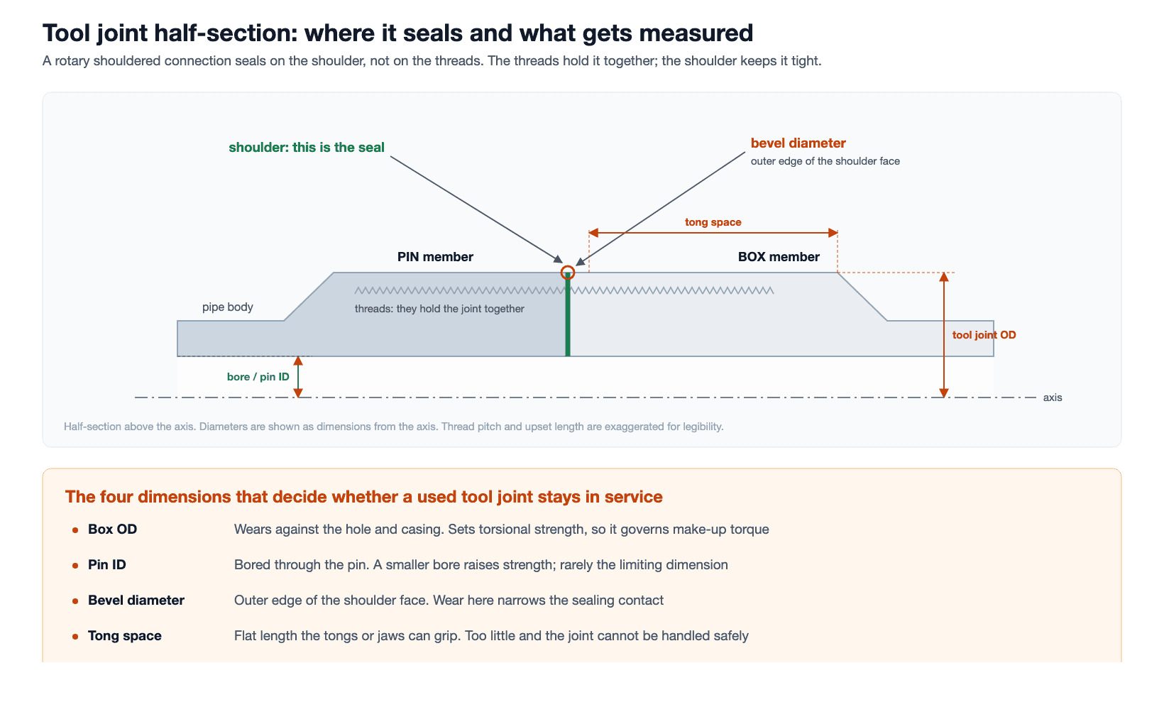
The sealing mechanism is worth being precise about, because it is the opposite of how casing and tubing behave. On an OCTG connection the thread helix is the leak path and compound fills it, as set out in the guide to buttress thread and OCTG connection types. On a rotary shouldered connection the threads are a coarse tapered form with deliberate crest-to-root clearance, which is exactly why the thread helix cannot be the seal. The flanks bear tightly and carry the tension; the job of the thread is to pull the two shoulders together and hold them under preload. Make-up torque exists to generate that preload.
Two consequences follow. A tool joint with perfect threads and a damaged shoulder will leak or fail. And a connection that has shouldered but stopped short of its make-up torque is preloaded, just not enough: rotation past the shoulder is what generates the clamp load, and torque is how you measure it. A low final torque means a low preload, and the shoulder separates under the first service load that exceeds it.
Drill pipe thread chart: NC designations and their older names
The thread chart below maps each NC designation to the legacy names it also carries. This is where most confusion lives. The industry accumulated several naming systems, and a single physical connection often carries a name from each. The NC series was introduced to rationalise it, and an NC number is not arbitrary: it is the thread pitch diameter at the gauge point, in inches, multiplied by ten and truncated. NC50 sits at 5.04 in, NC46 at 4.63 in, NC31 at 3.18 in, so the digits locate the connection rather than state it exactly.
| NC designation | Also known as | Commonly found on |
|---|---|---|
| NC26 | 2⅜ IF | 2⅜ in drill pipe |
| NC31 | 2⅞ IF | 2⅞ in drill pipe |
| NC38 | 3½ IF | 3½ in drill pipe |
| NC40 | 4 FH | 4 in drill pipe |
| NC46 | 4 IF, 4½ XH (also written 4½ EH), 4 WO | 4½ in drill pipe |
| NC50 | 4½ IF, 5 XH (also written 5 EH) | 5 in drill pipe |
The legacy abbreviations describe how the connection was originally intended to be used rather than its dimensions:
- IF, Internal Flush. Designed so the bore through the connection matches the pipe bore closely, favouring flow area.
- FH, Full Hole. An older style that also favoured bore, with different proportions.
- XH, Extra Hole (also written EH). Another bore-favouring family, and the source of much of the duplication above.
- WO, Wide Open, and SH, Slim Hole. Two further legacy families that also map onto NC numbers.
- REG, Regular. A stronger, smaller-bore family still common on drill collars, bits and subs.
The practical rule is that a name alone is not a specification. Two joints stencilled 4½ XH and NC46 will make up together because they are the same connection, but “4½ inch connection” tells you nothing, since 4½ IF and 4½ XH are different threads. Always order and inspect against the NC designation where one exists.
One more identification habit worth building. Stencils fade, get painted over and get copied wrong between yards, so treat the paint as a hint and the gauge as the answer. A pin gauge and a box gauge for the connection you think you have will settle it in under a minute, and they cost far less than one joint made up to the wrong torque or one string that has to come out of the hole.
The dimensions that actually govern
| Dimension | What it controls | Why it changes over time |
|---|---|---|
| Box outside diameter | Torsional strength of the box, and therefore the make-up torque the joint can carry | Abrasive wear against the hole wall and casing |
| Pin inside diameter | Tensile and torsional strength of the pin | Fixed at manufacture; only changes if the pin is rebored |
| Bevel diameter | The outer limit of the shoulder contact face | Falls as the tool joint OD wears; once it drops below the API value a fresh bevel must be cut |
| Tong space | Whether the joint can be gripped safely | Reduced by repeated refacing, which shortens the joint |
| Refacing benchmark | How much has already been dressed off the shoulder face | Each refacing cut moves the face back toward the benchmark step |
Box OD is the one to watch. Torsional capacity falls as the box wears thinner, so a worn tool joint cannot carry its original make-up torque even though the connection designation has not changed. This is the mechanism behind a common and expensive mistake: looking up the torque for a connection type, applying it to a worn joint, and yielding the box.
Torque figures are published against connection and tool joint dimensions together, which is why the same NC50 connection has more than one torque value depending on the box OD and pin ID it was cut on. The reasoning is covered in drill pipe make-up torque.
Hardbanding: protection with a cost
Because box OD wear is the limiting factor, most tool joints carry hardbanding: a band of wear-resistant weld deposit applied to the box outside diameter. It sacrifices itself instead of the parent metal.
| Consideration | What to check |
|---|---|
| Casing friendliness | Whether the product is rated to run inside casing without cutting it |
| Proud or flush | How far it stands above the box OD, which affects casing wear and tong grip |
| Condition | Missing sections concentrate wear on the parent metal beside them |
| Reapplication history | Repeated application can build up dimensions and eat tong space |
Hardbanding is routine maintenance rather than a repair. The point at which it stops being worthwhile is when the parent box OD beneath it has already worn past its own limit, at which stage the band is protecting metal that is already below specification.
Stress relief features, and the failure they exist to prevent
Rotary shouldered connections do not usually fail in the middle of the thread. They fail at the last engaged thread, where the load transfers abruptly from one member to the other and the section changes. That point is a stress concentration, and it sits in a component that is rotating and bending thousands of times an hour.
Two machined features exist purely to soften that transition, and you will see both called out on a tool joint drawing.
| Feature | Where it is | What it does |
|---|---|---|
| Stress relief groove | On the pin, behind the last thread | Removes the shallow unengaged threads so the load transfers into a smooth cylindrical section rather than a thread root |
| Boreback box | Inside the box, behind the threads | Bores out material to make the box end more flexible, spreading load over more threads instead of concentrating it on the first |
Both remove metal from a connection, which sounds like the wrong direction. They do reduce static strength slightly, and they earn it back many times over in fatigue life, which is what actually limits a drill string in a deviated hole. Severe service specifications commonly require them on larger connections for that reason.
Two practical consequences for a workshop. First, these features are part of the connection specification, so a recut has to reproduce them; a joint recut without its stress relief groove is not the connection it was. Second, they are a useful identification clue. A pin with a plain cylindrical relief behind the threads and a box with a visible counterbore tell you the joint was made to a severe service specification, which is worth knowing before you decide what torque to apply and whether to accept it back into a string that will see doglegs.
The interaction with refacing matters too. Every time a shoulder is dressed back, the relationship between the shoulder face and those features shifts slightly, which is one more reason the refacing benchmark is recorded rather than estimated.
Symptoms that are not the connection’s fault
| Symptom | More likely cause | Check first |
|---|---|---|
| Joint parts in the string | Fatigue in the slip area of the pipe body, not the connection | Pipe body grading and slip damage |
| Connection will not reach torque | The pin never reached the shoulder: cross-stab, stretched threads, or slipping jaws | Whether the curve shows a shoulder at all |
| Torque arrives early or the rise is stepped | Galling. Friction is climbing, so the number is reached with the shoulder under-loaded | The curve shape before the torque number |
| Repeated back-off downhole | Under-torque at make-up, or a torque figure taken from the wrong table | The recorded final torque against the tool joint dimensions |
| Shoulder damage on arrival | Handling and protector discipline in transit | Receiving inspection records |
| Two joints will not stab together | Different connections sharing a similar size name | The NC designation on both members |
That last row is one of the most common failures on mixed inventory. A yard holding 4½ IF and 4½ XH pipe has two incompatible connections whose stencils differ by two letters. The obvious mismatches will not stab at all. The dangerous ones will: API lists connections close enough to mate but not to carry the load, such as NC31 against 2⅞ XH, or any pair whose pitch diameters fall within 0.06 in. That is why the check is a gauge and the NC designation, not whether the two members went together.
Inspecting and reworking a used tool joint
- Identify the connection from the stencil and confirm it against a gauge rather than trusting the paint.
- Measure box OD and compare against the limit for that connection, not a general figure.
- Measure pin ID, since a rebored pin changes the torque the joint can take.
- Inspect both shoulder faces for galling, raised metal and flatness.
- Measure from the shoulder to the API refacing benchmark, which is what records how much has already been dressed off. Check bevel diameter separately, against OD wear.
- Confirm remaining tong space is enough for the equipment that will grip it.
- Inspect threads for wear on the load flanks and for any sign of stretch on the pin.
- Record the torque used at make-up against the joint identity, so the next shop is not guessing.
Steps two and three are the ones that make step eight meaningful. A torque figure without the dimensions it was derived from is a number with no provenance, and the next crew has no way to tell whether it was right.
Break-out on a used tool joint is its own hazard. A connection that has been downhole has usually been tightened further by drilling torque, and has lost its compound to washout, corrosion and adhesion. It can take substantially more torque to open than it took to close, which is why break-out capacity is specified above make-up capacity and the two are quoted separately. That is workshop work on equipment built for it rather than something to improvise, because a joint opened badly adds shoulder damage to a joint that may otherwise have been serviceable. That is workshop work on equipment built for it.
Frequently asked questions
What is a tool joint on drill pipe?
The forged connector welded to each end of the pipe, carrying a box at one end and a pin at the other. It is thicker and stronger than the pipe body and it is what actually joins one length to the next.
Does the thread seal a tool joint?
No. The two shoulder faces seal it when make-up torque presses them together. The threads are a coarse tapered form whose job is to generate and hold that preload.
What does NC mean in NC50?
Numbered Connection. The digits are the thread pitch diameter at the gauge point, in inches, multiplied by ten, so NC50 sits at roughly a five inch pitch diameter.
Is 4½ XH the same as NC46?
Yes, those are two names for the same connection, along with 4 IF and 4½ EH. Note that 4½ IF is a different connection and corresponds to NC50, which is exactly why size-and-letter naming causes trouble.
Why does the same connection have different make-up torques?
Because torque is published against the tool joint dimensions, not the connection name alone. The figures and how to read them are set out in drill pipe make-up torque.
What is bevel diameter used for?
It marks the outer edge of the shoulder contact face, and it falls as the tool joint outside diameter wears. Once it drops below the API value a fresh bevel has to be cut. It is not a record of refacing: that is what the API refacing benchmark is for, measured from the shoulder face.
Can a worn tool joint be repaired?
Often. Shoulders can be refaced, threads recut and hardbanding reapplied. Box OD worn below its limit cannot be restored on that tool joint, because hardbanding adds wear material rather than parent metal. The remedies then are downgrading the joint or cutting the tool joint off and welding a new one on, which is a mill operation rather than a shop repair.
Equipping a shop that handles tool joints
If a workshop has to make up and break out these connections rather than send them out, send the job envelope rather than a model number:
- OD range measured across the tool joint, not the pipe body
- Connection families handled: NC, REG, FH, H-90 or a mix. Give the NC designation, since IF, XH, SH and DSL names all resolve to one
- Break-out torque margin for connections that have carried preload in service
- Available tong space on the smallest joint you run
Send that envelope rather than a model number, and see how the machine side is specified for torque-controlled make-up and break-out.
Collar connections are cut into the body rather than onto a welded connector, which is covered alongside collar sizing in drill collar weight and selection.
Short checklist
- A tool joint is a rotary shouldered connection: the shoulder seals, the threads hold
- NC digits are the pitch diameter at the gauge point in inches, times ten and truncated
- One connection can carry NC, IF, XH and WO names at once
- 4½ XH equals NC46; 4½ IF equals NC50. The size alone tells you nothing
- Box OD governs the torque the joint can carry, and it wears
- Bevel diameter records how much refacing the joint has already had
- Record final torque against the joint identity and its dimensions
Expert Consultation
Need more information on optimizing your equipment performance? Our engineering team is available for technical consultations.
Request a Quote
Tell us about your requirements and our engineering team will prepare a detailed proposal with specifications, pricing, and delivery timeline.
