
Drill Pipe Make-Up Torque: 11 Checks Before You Trust the Number
A practical guide to selecting, correcting, applying, and recording drill pipe make-up torque without relying on a misleading universal torque chart.
Quick answer: Drill pipe make-up torque is the controlled torque used to preload a rotary-shouldered tool joint before it goes into service. The working value must come from the current performance sheet for the exact connection and tool-joint geometry, then be checked against the thread-compound friction factor, pipe condition, and equipment setup. A number copied from a chart without those checks can be precise and still be wrong.
Ask three people for a drill pipe torque chart and you may receive three different answers. One may apply to new tool joints, another to worn geometry, and a third to a different compound. The figures can look reassuring because they are printed to the nearest hundred foot-pounds. That appearance of accuracy is where trouble starts.
This guide is for workshop supervisors, drilling teams, QA staff, and buyers who need to understand what sits behind the target. It does not replace the pipe or connection manufacturer’s data. It shows how to turn that data into a controlled job rather than treating drill pipe make-up torque as a number to type into a machine and forget. On a hydraulic bucking unit with torque-turn recording the working value, the turns and the final torque are logged against each tool joint, which is the record this guide assumes you can produce.
Drill Pipe Make-Up Torque Guide
What Drill Pipe Make-Up Torque Actually Does
A rotary-shouldered connection seals and carries load through the relationship between its threads and shoulders. As the pin enters the box, the shoulders come together and the final part of make-up creates preload in the connection. The goal is enough shoulder contact and connection preload to resist service loads without taking the tool joint beyond its approved limit.
Too little torque can leave the joint vulnerable to further make-up downhole, shoulder separation, or movement under changing loads. Too much can overstress the weaker connection member, distort the shoulder, damage threads, or consume margin that the designer intended to retain. The correct target is therefore a defined connection value, not a general rule based only on pipe outside diameter.
NOV’s guidance on making up drill pipe connections tells crews to use the performance specification, apply sufficient make-up torque before running, and account for thread-compound friction factor. The same guidance warns that drill-string dynamics can drive unwanted downhole make-up when the initial connection preload is inadequate.
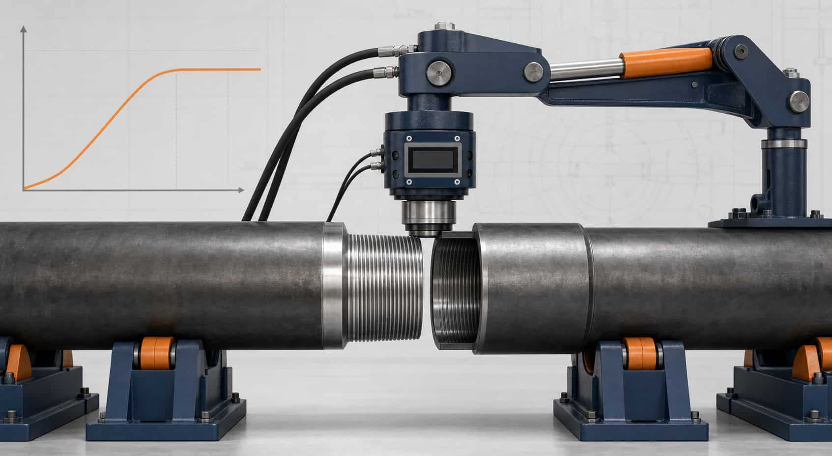
11 Checks Before Using a Drill Pipe Make-Up Torque Value
1. Identify the Exact Connection and Tool-Joint Geometry
Begin with the connection name, pipe size, tool-joint outside diameter, tool-joint inside diameter, material strength, and current condition. “Five-inch drill pipe” is not enough information. Two assemblies with the same pipe-body size can carry different tool joints and require different values.
The same applies to material, because non-magnetic collar material properties sit well below alloy steel on yield and hardness, so a steel drill collar figure cannot be carried across to a non-mag body.
Record what is physically present, not what the last job sheet says should be present. Tool joints can be recut, hardbanding can be renewed, and outside diameter can reduce with wear. If the markings and paperwork disagree, place the joint on hold until the identity is resolved.
2. Use the Current Manufacturer Performance Sheet
A generic chart is useful for learning terminology. It should not outrank the current sheet for the actual product. Manufacturer documents often separate recommended torque, maximum torque, torsional yield reference, new geometry, worn geometry, and different friction factors. Read the notes under the table; that is often where the assumptions are stated.
For example, current TSC drill-pipe data sheets publish connection-specific values and clearly tie them to tool-joint geometry and compound friction factor. The point is not to copy one of those figures into a different job. The point is to see how many inputs sit behind a legitimate value. Keep the applicable sheet with the work order and note its revision.
3. Separate Recommended, Minimum, Maximum, and Operating Torque
These terms answer different questions. Recommended make-up torque is a target for assembling the connection under stated assumptions. A minimum value may define the lower acceptable boundary. Maximum make-up torque is a ceiling that must not be exceeded. Operating or drilling torque describes load during service and is not a substitute for the assembly target.
NOV’s guide to reading its drill-pipe performance sheets explains that operating torque and make-up torque must be considered together. Treating the highest number on a page as the machine setting is a fast way to misuse a sound engineering document.
4. Confirm the Thread-Compound Friction Factor
Thread compound changes the relationship between applied torque and connection preload. That is why drill pipe make-up torque values are commonly tied to a stated friction factor. The product name on a pail is not enough; obtain the current technical data for the compound and confirm that it is approved for the connection.
NOV notes that its values are generally based on a friction factor of 1.0 unless stated otherwise, and its thread-compound application guidance explains both coverage and adjustment. The connection supplier may limit the permitted correction even when the compound supplier lists a higher factor, so follow the more specific instruction.
A simple illustration shows the effect. If an approved base value were 30,000 ft-lb at a factor of 1.0 and the authorized correction factor were 1.15, the corrected target would be 34,500 ft-lb. That arithmetic is easy. Confirming that the base value, factor, and allowed cap all belong together is the real work. Never use this example as a job value.
5. Inspect and Clean the Connection Before Make-Up
Torque cannot compensate for a damaged shoulder, contaminated thread, or wrong protector. Remove storage compound by the approved method, inspect the pin and box, and check the primary shoulder, secondary shoulder where fitted, thread starts, seals, and tong areas. Reject improvised cleaning that removes metal or changes surface finish.
Look for dents, raised material, galling, corrosion, embedded grit, hard contact marks, and evidence that the connection was stabbed off-center. If a defect needs acceptance criteria, stop and route it to the responsible inspector. A smooth machine cycle does not turn a questionable connection into an acceptable one.
6. Control Alignment, Stabbing, and Initial Rotation
The pipe should be supported on the connection centerline before rotation begins. Misalignment can load the first engaged threads, create false resistance, and leave marks that only become obvious after break-out. Stab slowly, confirm free engagement, and use a spinner only within the connection and equipment procedure.
Watch the first turns. A connection that hesitates, cocks to one side, or needs unusual spin torque is asking for inspection. Back it out before high torque is applied. Operators sometimes feel pressure to “see if it cleans up”; that gamble can convert a recoverable alignment problem into thread damage.
7. Put the Jaws in Approved Clamping Areas
Jaw position and clamp pressure affect both safety and the condition of the tool joint. Keep the gripping system clear of shoulders, seals, hardbanding transitions, thin sections, and restricted tong-free areas. Match the dies or low-marking inserts to the surface and load.
A slipping jaw does not automatically mean “add more pressure.” The die may be wrong, dirty, worn, or sitting on an unsuitable area. The support height may also be pushing the component out of line. Correct the setup rather than forcing the clamp to hide it.
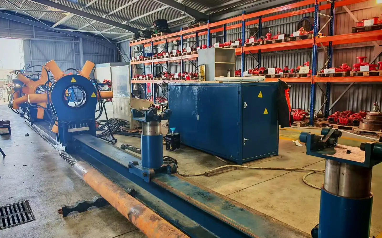
8. Verify Calibration and the Complete Measurement Chain
A current calibration sticker is necessary, but it does not prove the whole system is correct. Confirm the load cell or pressure transducer, signal conditioning, displayed units, software scaling, effective lever arm where applicable, and the relationship between the indicated value and actual connection torque.
When conventional tongs are used, torque depends on line pull and the effective tong-arm length. SLB’s drilling glossary describes tongs as opposing wrenches used to grip drill-string components and apply torque. If the pull direction or effective length changes, the calculation changes too. A workshop torque machine usually calculates this internally, but its geometry and sensor configuration still need verification.
9. Control Make-Up Speed and the Final Approach
Fast spinning and final torquing are different phases. Use spin speed to close distance only where the procedure allows it, then slow the connection before shoulder engagement and final loading. The control system should approach the target without a large overshoot.
Review how the machine stops. Hydraulic response, valve timing, rotating inertia, software sample rate, and a heavy workpiece can all affect the final value. If the target is reached only after a sharp spike, the display may be showing the consequence of poor control rather than a clean make-up.
10. Watch the Connection Behavior, Not Just the Final Number
A connection can finish at the target and still behave abnormally on the way there. Pay attention to turns, torque rise, shoulder engagement, stalls, sudden jumps, repeated slip, and any change from a known good connection of the same type. Where the procedure calls for a torque-turn graph, apply its acceptance window rather than judging the curve by appearance.
This is where a recorded system earns its keep. Galip’s guide to OCTG handling and storage follows connection condition before it reaches make-up. The torque record continues that chain: it helps show whether the prepared connection behaved as expected under load.
11. Record Enough Information to Reconstruct the Job
A final drill pipe make-up torque value without context is a weak record. Capture the joint or component identity, connection, tool-joint dimensions, performance-sheet reference, compound and batch, friction factor, target and limits, machine ID, calibration status, operator, date, result, and disposition.
If the equipment records torque and turns, keep the original data as well as the PDF report. Note any break-out, inspection, reapplication of compound, or second make-up. A clean audit trail should distinguish a first-pass connection from one that required correction.
How to Use a Drill Pipe Make-Up Torque Chart Without Misreading It
| Question | What to verify | Common mistake |
|---|---|---|
| Which product? | Connection family, pipe size, tool-joint OD and ID, strength, wear condition | Selecting by pipe OD alone |
| Which value? | Recommended, minimum, maximum, or operating torque | Using the largest number as the target |
| Which compound? | Approved product, friction factor, supplier instructions | Changing compound without correcting the value |
| Which revision? | Current manufacturer performance sheet and job procedure | Using an old screenshot with no revision |
| Which units? | ft-lb, lbf-ft, N·m, or kN·m and the machine display setting | Entering a converted number in the wrong unit mode |
Unit mistakes deserve special attention. Foot-pounds and newton-metres are not interchangeable, and “lb-ft” on a document may be written differently from the machine screen. Put the required unit on the work instruction, keep the conversion controlled, and use an independent check when a value has been converted manually.
A Practical Drill Pipe Make-Up Torque Record
- Job number and customer
- Component and serial or joint identity
- Pipe size, grade, and condition class
- Connection name and tool-joint OD/ID
- Performance-sheet document number and revision
- Thread compound, batch, and approved friction factor
- Base torque, corrected target, lower limit, and upper limit
- Machine, jaw set, support arrangement, and software recipe
- Calibration certificate numbers and due dates
- Operator and inspector
- Final torque, turns or curve file, result, and disposition
This list looks longer than a single set-point field because the job contains more than a set point. Once the template is built into the workshop system, most fields can be selected or scanned rather than typed. That reduces operator workload and prevents a good procedure from becoming a paperwork exercise.
What Drill Pipe Make-Up Torque Equipment Must Be Able to Prove
The machine must cover the connection’s real torque range with useful accuracy near the target, not merely advertise a large maximum. It also needs suitable gripping, stable supports, controlled low-speed approach, an emergency stop, visible guarding, and a measurement system that can be calibrated as a complete chain.
For workshop make-and-break work, Galip’s hydraulic breakout equipment can be configured around pipe range, torque capacity, support length, gripping method, and reporting needs. The right specification starts with the connection list and required records. It should not start with the biggest torque figure in a brochure.
Frequently Asked Questions
Is there one universal drill pipe make-up torque chart?
No. Charts depend on connection type, tool-joint geometry, material assumptions, wear condition, and thread-compound friction factor. Use the current document for the exact product and verify its notes.
Does pipe grade alone determine the torque?
No. The tool joint and connection geometry are central to the value. Pipe-body grade and condition still matter to the assembly’s overall limits, which is why the complete performance sheet must be reviewed.
What happens when the thread compound changes?
The required correction may change. Confirm the compound’s friction factor, connection approval, and any cap stated by the connection manufacturer before revising the job target.
Should break-out torque equal make-up torque?
Do not assume that it will. Break-out is influenced by compound behavior, time, temperature, loading, corrosion, surface condition, and connection design. Evaluate it under the applicable procedure rather than using it as a simple pass/fail copy of the make-up target.
Is the final torque number enough for acceptance?
Sometimes a procedure uses torque-only acceptance, but the setup and connection condition still matter. When torque-turn acceptance is required, the recorded curve and connection-specific window are part of the decision.
The Number Is the End of the Decision, Not the Beginning
Good drill pipe make-up torque control begins with identification and ends with a traceable record. Between those points sit the performance sheet, compound, inspection, alignment, gripping, calibration, speed, and operator response to abnormal behavior.
That chain is what makes the final number credible. When any link is missing, stop and resolve it before the connection goes into service. A five-minute check at the machine is cheaper than explaining a damaged tool joint after the string is already committed to the job.
Torque figures assume the joint is in class, which is why remaining wall and inspection grading is worth checking before a used string goes back to work.
Torque figures are keyed to the connection and its dimensions, which are explained in tool joint connection types and wear limits.
Technical References
Expert Consultation
Need more information on optimizing your equipment performance? Our engineering team is available for technical consultations.
Request a Quote
Tell us about your requirements and our engineering team will prepare a detailed proposal with specifications, pricing, and delivery timeline.
