
Directional Drilling: How a Well Is Steered, and Which of Its Tools Are Made Up Before the Rig
Most wells drilled today are steered. This page explains the directional well profile, how a mud motor with a bent housing and a rotary steerable system steer the bit, how MWD tells the driller where the bit is, and why every steering tool is a threaded assembly that was made up on a bench before…
Directional drilling is drilling a well along a planned path rather than straight down: vertical to a kickoff point, a curved build section, then a hold or a horizontal lateral through the reservoir. The bit is steered by a mud motor with a bent housing or a rotary steerable system, guided by measurement-while-drilling surveys. All three are threaded tool assemblies, made up and tested before the rig picks them up.
At a glance
| What it is | Controlling the path of the hole so that it reaches a target the rig is not sitting over: a reservoir offset from the surface location, several targets from one pad, or a long horizontal section inside a thin pay zone |
| The profile | Vertical to the kickoff point, a build section at a planned build rate in degrees per 100 ft, a tangent or hold section, sometimes a drop, and for a horizontal well a landing at about 90 degrees followed by the lateral |
| How the bit is steered | A mud motor with a bent housing, sliding to build angle and rotating to drill straight; or a rotary steerable system that steers while the whole string turns. Either way a measurement-while-drilling tool surveys the hole and sends inclination and azimuth to surface |
| What is threaded | The motor’s power, transmission and bearing sections, the bent housing, the MWD pressure housing, the non-magnetic collars around it, the stabilizers and every sub between them. Each is a rotary shouldered connection made up to a torque |
| Decision this page supports | Understanding why directional tools go through a yard or service shop before and after every run, and what that shop’s bench has to do with the quality of the hole |
What directional drilling is
A vertical well goes where the rig is. Most of the wells drilled today go somewhere else: under a lake, a town or a platform’s reach, into a reservoir that lies to one side, or sideways along a thin layer of rock for a kilometre or more so that one well drains what twenty vertical wells once would. Directional drilling is the set of tools and methods that steer the bit along a planned path to a target, and horizontal drilling is its most common modern form, a well that turns through ninety degrees and runs level through the pay zone. The industry’s own primer sets out the practice and the hardware behind it (SLB Oilfield Review, Defining Series: Directional Drilling Practices).
The steering happens at the bottom of the drill string, in the bottom hole assembly, and that is where this page spends its time. The assembly is a stack of threaded tools, motor, bent housing, stabilizers, measurement tools in non-magnetic collars, subs, and the question a workshop cares about is where that stack was put together and taken apart. The answer is a bench, before and after every run, which is why the directional business keeps more service shops than rigs.
The well profile: kickoff, build, hold, lateral
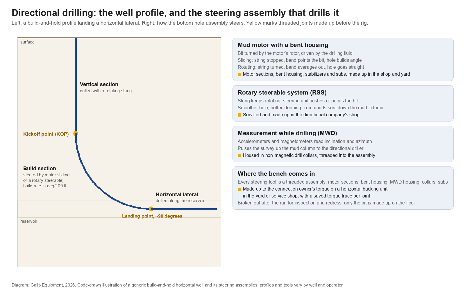
A directional well is planned as a sequence of sections. The hole is drilled vertically to the kickoff point, the depth at which the inclination begins to change. From there the build section curves the hole at a planned build rate, stated in degrees per 100 ft; conventional wells build at a few degrees per 100 ft, and a build rate much above that is a dogleg that drill pipe and casing must be checked against. A hold or tangent section keeps inclination and azimuth constant toward the target. An S-shaped well adds a drop section back toward vertical before the target; a horizontal well instead lands at about 90 degrees and continues as a lateral inside the reservoir (Drilling Manual, Types of Directional Well Profiles). A shallower kickoff needs a gentler build; a deeper one needs a sharper build to reach the same target, which is why the kickoff is usually planned in soft, shallow formation.
Each section is drilled with a different intent and often a different assembly. The vertical section is drilled with a rotating string and a stiff, stabilized assembly that resists deviation. The build section is where the steering tools earn their keep. The lateral is drilled with a low-bend motor or a rotary steerable system holding inclination at high rates of penetration. The directional driller’s job is to keep the hole on the planned curve, and the surveys that tell him where the bit is come from the measurement tool described below.
How the bit is steered: mud motor with a bent housing
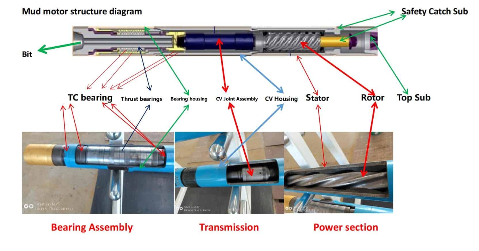
The oldest steering method still in wide use is a positive displacement mud motor fitted with a slight bend in its housing, a degree or two, just above the bit. Drilling fluid pumped down the string turns the motor’s rotor inside its stator, and the rotor turns the bit, so the bit can drill while the drill string above the motor stays still. With the string stopped, the bend points the bit a little off the hole axis and the hole curves in that direction: this is sliding, and it builds or turns angle. With the string rotating, the bend sweeps around the hole and its effect averages out, and the hole goes straight. The directional driller alternates sliding and rotating to follow the plan, orienting the bend with the string between slides (Drilling Contractor, Directional Drilling System Combining Mud Motor and MWD). Higher bends build faster but limit how fast the string can be rotated with the bend in it; low bends are used in laterals where the hole has to be held rather than turned.
The motor is a Galip product line as well as a steering tool, and the pages on how a mud motor works, the bearing assembly and rotor-stator fit go through the sections one by one. For this page the point is their construction: a motor is a power section, a transmission, a bearing section and a bent housing, threaded to each other, with a rotary shouldered connection at each end to the rest of the assembly.
How the bit is steered: rotary steerable systems
A rotary steerable system steers without stopping the string. A unit just above the bit either pushes against the hole wall with pads or points the bit by flexing a shaft inside its housing, while the whole drill string keeps turning. Commands go down to the tool as pressure pulses in the mud column; the tool holds the planned direction and the driller corrects it from surface. The benefits are a smoother hole, better hole cleaning because the string never stops rotating, and more accurate control over long laterals, at a higher day rate than a motor. Many assemblies run a motor and a rotary steerable together, the motor adding rotation at the bit while the steerable unit does the pointing.
Whichever method is used, the tool is a threaded assembly owned by a directional service company, and it goes back to that company’s shop after the run.
Measurement while drilling: knowing where the bit is
Steering is useless without a survey. A measurement-while-drilling tool sits in the assembly above the steering unit and measures inclination with accelerometers and azimuth with magnetometers, then pulses the readings up the mud column to the rig floor, where the directional driller compares the actual path with the plan. Because the magnetometers read the Earth’s field, the sensors have to be carried in drill collars that are not magnetic; the number of non-magnetic collars needed, and why, is set out in non-magnetic drill collar spacing, and the collars themselves are described on the non-magnetic drill collar product page. Logging-while-drilling tools add formation measurements to the same string, so that the driller can land the lateral in the right rock and keep it there.
The MWD tool is electronics in a threaded pressure housing, run inside the non-magnetic collar. Between the housing, the collar, the stabilizers and the subs that space them, the measurement part of the assembly alone carries half a dozen rotary shouldered connections, each with a torque in the owner’s manual.
The steering tools are threaded assemblies
Lay the bottom hole assembly out on a rack and count the connections: bit to motor, motor section to motor section, bent housing to bearing section, motor to stabilizer, stabilizer to non-magnetic collar, collar to MWD housing, housing to collar, collar to crossover, crossover to heavy-weight drill pipe. Twenty joints is normal. Only the first, the bit, is made up on the rig floor, with a bit breaker. The rest were made up before the rig picked the assembly up, and the directional company’s shop made up most of them: the motor during its last service, the MWD during its build, the collars and subs in the yard when the assembly was dressed for the well. The general case for where drill string connections are made is set out in drill string components; the directional assembly is the part of the string where the shop’s share is largest.
| Tool | Its threaded connections | Where they are made up, and what the record is |
|---|---|---|
| Mud motor | Power section to transmission, transmission to bearing section, bearing section to bent housing, plus the end connections | In the motor shop at every rebuild, on a horizontal bench, to the maker’s internal torques; the end connections in the yard when the assembly is dressed |
| Bent housing and stabilizers | Rotary shouldered connections top and bottom | In the yard, to the connection tables, when the assembly is built for the well; the bend setting is recorded with the make-up |
| Non-magnetic collars | Rotary shouldered connections, often with a proprietary bore or slot for the MWD | In the yard, with the thread compound the non-magnetic alloy requires and a torque record; galling is the risk on these materials |
| MWD pressure housing | Internal connections joining the electronics sections, and end connections to the collar | In the MWD shop at build and at every service, to the maker’s manual; the end connections in the yard |
| Rotary steerable unit | End connections, and internal housings serviced by the owner | In the owner’s service centre between runs; in the yard for the end connections |
| Bit | One pin, to the bit sub or motor | On the rig floor with a bit breaker, to the bit maker’s table; the only floor make-up in the assembly |
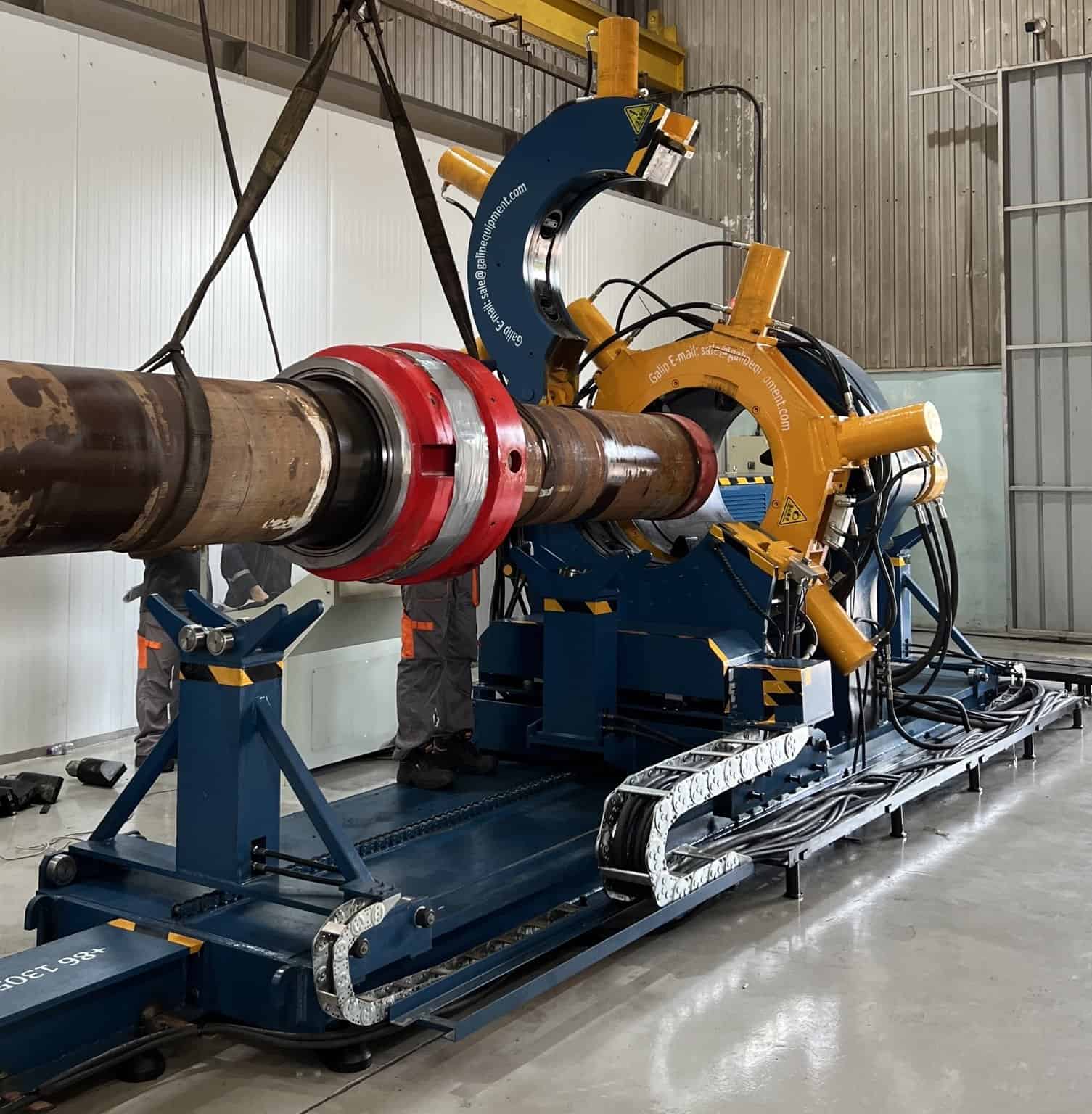
The bench behind that table is a horizontal hydraulic bucking unit: the tool is loaded and supported, clamped on jaws chosen for its body, brought up to the connection’s shoulder and torque, and the trace saved against the tool’s serial number. Three things make directional tools harder than plain collars. Their bodies carry electronics, bends and bearing packs that must not be crushed or strained in the jaws. Their non-magnetic alloys gall more readily than steel, so compound and speed matter. And their internal connections are proprietary, with torques that come from the maker’s manual and from nowhere else. A motor that comes back from a run goes through the same bench in reverse, every joint broken out so the sections can be inspected, which is why the shop sizes its machine from break-out and keeps a breakout unit where motor volumes are high, as the page on breakout units for mud motor repair describes.
After the run
A directional assembly is run for one section of hole, pulled, and laid down, and the whole of it goes back to a shop. The motor is stripped: stator inspected for chunking and swelling, rotor for wear and coating damage, bearings for play, the bent housing for cracks at the bend. The MWD is downloaded and its electronics serviced. The collars and stabilizers are inspected, gauged and re-dressed. Every one of those steps begins by breaking a threaded connection and ends by making one up again, with a record, and the assembly that goes out to the next well is a new set of make-ups. The downhole tools page follows that cycle for the whole fleet; the directional tools are the part of it that turns over fastest.
Where directional drilling sits in the industry
Directional drilling is the drilling phase of the upstream oil and gas sector, and the directional service companies, with their motors, steerable tools and MWD fleets, are among the most workshop-intensive businesses in it. Horizontal directional drilling for pipelines and utilities uses the same principle with lighter tools, and Galip supplies sonde housings for that market; the two trades share the words and little else.
When another page is the better start
A directional driller planning a well profile, kickoff depth, build rate, dogleg limits, is working with well-planning software and the operator’s drilling programme, and this page adds nothing to that. A buyer specifying a mud motor should start on the motor product pages and the sizing guides. A directional service shop that already knows its tool range and connection types should go to the bucking unit product page and the acceptance checklist, and should ask about jaws for non-magnetic collars and motor bodies, break-out capacity, and trace export per tool serial. And a reader whose question was really the drill string as a whole should read the drill string components page first.
The usual limit applies. Build rates, bend settings and internal torques belong to the well plan and the tool makers; this page describes where the tools are made up and taken apart, not what their numbers are.
Frequently asked questions
What is directional drilling?
Drilling a well along a planned path to a target that is not directly below the rig: vertical to a kickoff point, a build section that curves the hole at a planned rate, then a hold section or, for a horizontal well, a landing at about ninety degrees and a lateral through the reservoir. The bit is steered by a mud motor with a bent housing or a rotary steerable system.
How does directional drilling work?
A measurement-while-drilling tool surveys inclination and azimuth and sends them to surface. The directional driller compares the path with the plan and steers: with a bent-housing motor by sliding, string stopped and the bend pointing the bit, then rotating to drill straight; with a rotary steerable system by sending commands down the mud column while the string keeps turning.
What is the difference between directional and horizontal drilling?
Horizontal drilling is directional drilling whose profile lands the well at about ninety degrees and continues sideways through the reservoir. Every horizontal well is directional; a directional well may only be deviated to reach an offset target or follow an S-shaped path back to vertical. The tools and surveys are the same; the lateral adds the demand of holding angle over a long distance.
What does a mud motor do in directional drilling?
It turns the bit with the energy of the drilling fluid, so the bit can drill while the drill string above stays still. A slight bend in the motor housing points the bit off the hole axis; with the string stopped the hole curves, with the string rotating the bend averages out and the hole goes straight. Alternating the two is how a motor assembly follows the plan.
What is MWD?
Measurement while drilling: a tool in the bottom hole assembly that measures inclination with accelerometers and azimuth with magnetometers and pulses the survey up the mud column to the rig. Because the magnetometers read the Earth’s field, the tool is run inside non-magnetic drill collars. Logging-while-drilling tools add formation measurements to the same assembly.
Where are directional drilling tools made up?
Almost entirely off the rig. Motors, MWD housings and steerable units are assembled in their owners’ service shops at every rebuild, to the makers’ internal torques, and the assembly of collars, stabilizers, subs and tools is dressed for the well in the yard on a horizontal bucking unit, to the connection tables, with a torque record per joint. Only the bit is made up on the rig floor.
Send the tool list with the enquiry
A directional service shop is quoted from its fleet. The useful set for a bucking unit quotation is: the motor sizes and the longest and heaviest motor section, the non-magnetic collar sizes and connection types, the MWD housing dimensions, the highest make-up torque in the makers’ manuals and the highest break-out expected on tools returned from the hole, whether bodies need special jaws or supports, the record format per tool serial, the site power supply and a sketch of the make/break cell. The Galip team quotes from that list and will say where a breakout unit belongs beside the bench.
The directional drilling checklist
- Read the well plan for its sections: kickoff, build rate, hold, drop or landing and lateral; each decides which assembly is run.
- Know how the assembly steers, motor sliding and rotating or a rotary steerable, and what MWD it carries.
- Count the threaded connections in the assembly; expect around twenty, of which only the bit is made up on the floor.
- Make up motors, MWD housings and steerable units in their owners’ shops to the makers’ internal torques; dress the assembly in the yard to the connection tables.
- Use the compound and speeds non-magnetic alloys require, and record every make-up against the tool serial.
- Size the shop’s bench from break-out on tools returned from the hole, and add a breakout unit where motor volumes justify it.
- Inspect every section at strip-down: stator, rotor, bearings, bend, electronics, collars.
- Keep the make-up record with the tool, because the next well’s directional driller is relying on it without knowing it.
Expert Consultation
Need more information on optimizing your equipment performance? Our engineering team is available for technical consultations.
Request a Quote
Tell us about your requirements and our engineering team will prepare a detailed proposal with specifications, pricing, and delivery timeline.
