
Mud Motor Test Bench: How It Works and How to Run a Test
What a mud motor test bench is, how the flow loop and load unit work, and a step-by-step tutorial for running a full motor test with acceptance criteria.
Quick answer: A mud motor test bench is a workshop rig that spins a downhole motor under controlled flow and load so you can measure what it actually delivers — RPM, torque, and differential pressure — and check whether anything leaks. You mount the motor between a headstock and supports, circulate fluid through it, load the output shaft in steps, and record the curve. If the motor can’t hold its rated numbers on the bench, it isn’t ready for the hole.
A mud motor that fails on the bench costs you an afternoon. The same motor failing downhole costs a round trip, and a round trip in rig time often costs more than the motor repair — offshore, many times over. That one comparison explains why test benches exist, and why serious repair shops won’t ship a motor without a bench run. The smaller cousins of this bench serve coiled tubing downhole tools, where every component is proved at surface before a blind single-trip run.
The same arithmetic applies to drilling jars, which is why service shops load and cycle them on a bench tester for drilling jars before the tool is signed off.
If you’ve just inherited a bench, you’re comparing test stands to buy, or you keep signing off “tested OK” reports and want to know what’s actually behind them, this is for you.
What is a mud motor test bench?
A mud motor test bench (also called a drilling motor test bench, test stand, or motor dyno) is a horizontal workshop rig that holds a positive displacement motor while fluid is pumped through it, and measures the motor’s output torque, speed, and differential pressure under a controlled load. The point is to recreate downhole working conditions in the shop, where you can see the gauges, feel the vibration, and stop the moment something looks wrong.
A proper bench measures at least four things at the same time:
- Flow rate through the motor (which sets the speed)
- Differential pressure across the motor (which tracks the torque)
- Output torque at the drive shaft
- Output speed in RPM
Some benches add axial-load capability to simulate weight on bit, temperature sensors on the bearing housing, and vibration monitoring. But flow, pressure, torque, and speed are the core four. If a “test” only circulates fluid and confirms the shaft turns, that’s a function check, not a performance test. It will catch a seized motor and not much else.
There’s a reason the distinction matters. A motor with a chunked stator lobe or a worn power section will still spin happily with no load on it. The damage only shows up when you ask for torque. That’s exactly what the loading system on the bench is for.
How does a mud motor test bench work?
Everything on the bench follows from how a PDM works in the first place. The power section is a Moineau pump running in reverse: fluid forced through the rotor/stator profile makes the rotor turn. Two relationships fall out of that geometry, and they’re the key to reading any test:
Speed follows flow. The rotor turns a fixed number of revolutions for every liter that passes through. Double the flow, roughly double the RPM, load or no load.
Torque follows differential pressure. The harder the shaft resists turning, the more pressure it takes to push fluid through the power section. On the bench you read torque directly from the sensor, but the pressure gauge tells the same story, which is exactly why drillers use standpipe pressure as a torque gauge on the rig.
So the bench is built as a loop. A pump draws fluid from a tank and pushes it through a flow meter into the motor’s top sub. The fluid drives the power section and returns to the tank. Meanwhile the output shaft is coupled to a loading device, usually a hydraulic brake or dynamometer, that can resist rotation with a controlled, adjustable force. Between the motor and the brake sit the torque and speed sensors.
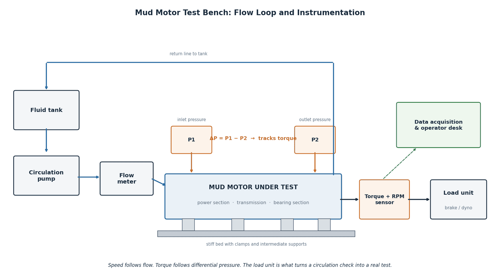
The operator’s job during a test is to hold flow steady, ramp the load in stages, and record what the motor does at each stage. Plotted out, that becomes the performance curve you compare against the motor’s datasheet.
Most workshop benches run clean water or a light water-based fluid, not actual drilling mud. That’s fine for verifying the power section and bearings, and it keeps the shop clean. Just remember the datasheet numbers were often set with specific fluid properties, so small differences between bench numbers and field numbers are normal. Also remember that rotor/stator fit is sized for downhole temperature: a power section fitted for a hot well runs measurably looser on an ambient water bench, so compare against the manufacturer’s curve for your actual test fluid and temperature, not just the headline catalog numbers. What you’re checking is whether the motor holds its rated torque without stalling early, leaking, or overheating.
The main parts, and what each one is for
The bed and clamps. A long, stiff frame with a headstock and intermediate supports. Downhole motors run from about 3 m to over 9 m long, so the bed has to keep the motor straight; a sagging motor puts side load on the drive line and corrupts the torque reading.
The circulation system. Tank, pump, valves, and a flow meter. The pump needs enough capacity to reach the motor’s rated flow. For a small-diameter HDD motor that may be a few hundred liters per minute. For a 244 mm (9⅝”) OD motor, you’re sizing for several thousand.
The loading unit. The part that separates a real test bench from a circulation loop. Hydraulic disc brakes and water-brake dynamometers are the common choices. It must apply load smoothly; a grabby brake creates torque spikes the motor never sees downhole.
Instrumentation. Pressure transducers before and after the motor, a torque/speed sensor on the output line, and a data acquisition system that logs everything against time. Calibration is not optional here. A torque sensor that reads 8% high will quietly pass a tired motor. Good shops keep a calibrated reference transducer and check the bench against it on a schedule.
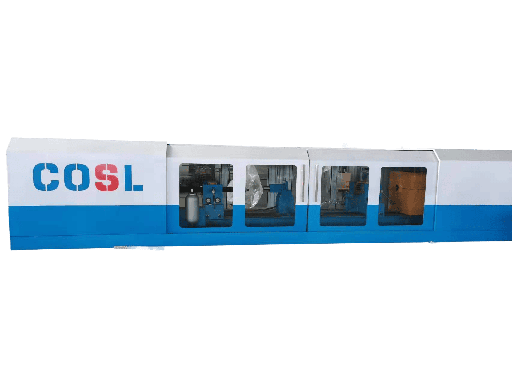
The enclosure. The test cell on the bench in the photo at the top of this page has full covers with polycarbonate windows for a reason. You have rotating machinery, pressurized hoses, and, if a connection lets go, fluid at pump pressure looking for an exit. The operator belongs behind the windows at the control desk, not leaning over the drive line.
How to test a mud motor: step by step
Every shop has its own procedure, and the motor maker’s manual always wins. But a bench day follows the same skeleton nearly everywhere:
- Pull the datasheet and identify the motor
- Inspect and measure bearing play, cold
- Mount, align, and connect
- Verify the instruments
- Run in at no load
- Load in steps at constant flow
- Verify rated torque; treat stall with respect
- Watch trends throughout
- Shut down and re-measure
- Write the report the same day
Step 1: Start with the paperwork
Identify the motor: serial number, size, lobe configuration, stage count, and the job it came from or is going to. Pull the datasheet so you know the rated flow range, rated torque, and expected pressure figures before you start. Testing against numbers you looked up afterward is how wishful thinking creeps into reports.
Step 2: Inspect before you connect
Check thread condition on both ends, look for dings on the housing, and measure the bearing axial play with a dial indicator while the motor is still cold. Write the number down; you’ll measure again after the run. Turn the shaft by hand if the size allows. It should turn with even resistance, no clicking, no free spots.
Step 3: Mount and align
Set the motor on the supports, clamp it, and couple the output shaft to the load line. Shim the supports until the motor sits straight and the output shaft lines up with the load line; any sag side-loads the coupling and corrupts the torque reading. Then connect the flow line to the top sub and make sure the return line back to the tank is clear and open before anyone touches the pump.
Step 4: Verify the instruments
Zero the torque sensor with the drive line free. Confirm the pressure transducers read zero (or ambient) with the pump off. Check the calibration dates.
Step 5: Run in at no load
Bring the pump up slowly to the low end of the motor’s flow range with the brake fully released. Let it run several minutes. You’re watching for three things: RPM in the expected range for that flow, a low and steady no-load differential pressure, and no leaks at the connections. The no-load pressure is worth recording; a power section that’s dragging shows it here first.
Step 6: Load in steps
Holding flow constant, apply the brake in planned increments, maybe five to eight steps up to rated torque. At each step, hold long enough for the numbers to settle, then log flow, ΔP, torque, RPM, and temperature. What you want to see: torque climbing in step with differential pressure, close to linear, while RPM stays near the no-load value and only sags slightly as load rises.
Step 7: Treat stall with respect
Some acceptance procedures require demonstrating stall torque, the point where the shaft stops while fluid keeps trying to force through. If yours does: approach it briefly, catch the peak reading, and release immediately. Holding a motor at stall destroys the stator: the lobes sit over-deflected under full differential pressure while fluid jets past the seal lines, and the elastomer can start to chunk within seconds. Many shops, ours included, prefer to verify torque at 100% of rated and confirm the stall margin by extrapolation rather than parking the motor at stall to prove a point.
Step 8: Watch trends, not just values
Through the whole run, keep an eye on bearing housing temperature and the pressure trace. A slow pressure climb at constant load can mean the stator is working too hard. Oscillation in the torque trace often points at the load line or coupling, not the motor. Note everything, and flag anything you can’t explain before the motor leaves the bench.
Step 9: Shut down and re-measure
Ramp the load off, then the flow, and let the motor drain. Measure the bearing play again while it’s warm and compare with the cold number from step 2, keeping in mind that part of any growth is thermal expansion of the bearing stack; judge both readings against the maker’s absolute limits, and if the warm number sits near the limit, re-measure after cool-down before condemning the bearing section. Check the shaft seal area for leakage. Break the connections and look at the threads one more time before the protectors go on.
Step 10: Write the report the same day
Serial number, date, fluid used, calibration references, the logged table, the curve, the play measurements, and a clear verdict: accepted, accepted with comments, or rejected with the reason. Attach the operator’s name. A test report nobody can trace to a motor, a bench, and a person is just a PDF.
Reading the performance curve
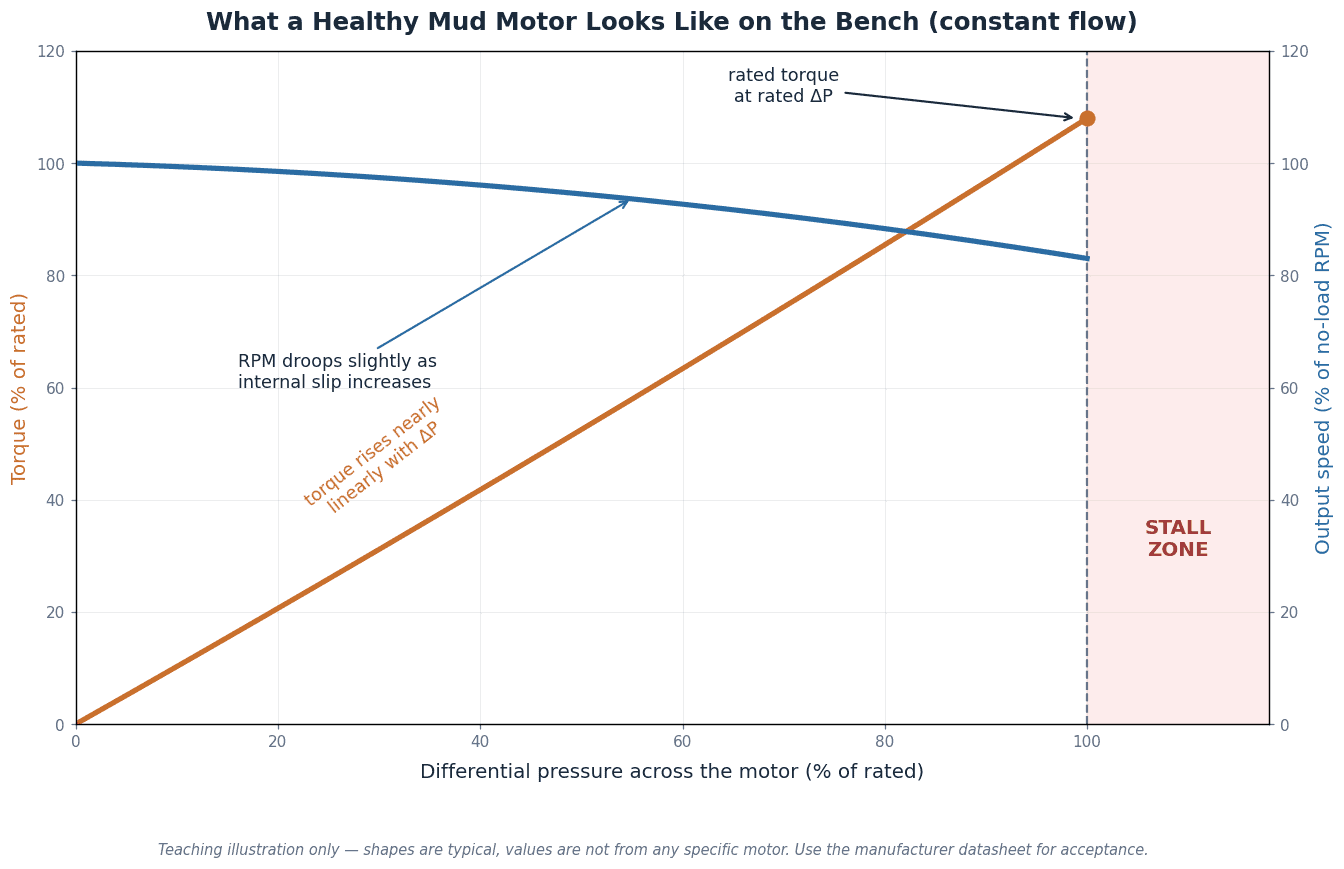
The plot that matters shows torque and RPM against differential pressure at constant flow. A healthy motor draws two clean lines. Torque rises almost linearly with ΔP, because that’s the geometry of the power section doing its job. RPM starts at the no-load speed for that flow and stays fairly flat, drooping a little as load increases, because some fluid starts to slip past the rotor/stator seal line under pressure.
The failure patterns are just distortions of those two lines:
| What you see on the bench | What it usually means | What to do |
|---|---|---|
| Torque line falls below datasheet from the start | Worn power section, wrong fluid assumptions, or a sensor problem | Verify calibration first, then suspect the stator |
| RPM droops hard at moderate load | Excessive internal slip: worn stator or rotor coating | Pull the power section for inspection |
| High no-load differential pressure | Internal drag: tight fit, bearing trouble, or debris | Stop and investigate before loading |
| Torque oscillates at steady load | Coupling or load-line issue, or a chunked stator lobe passing | Check the drive line, then the stator |
| Pressure climbs at constant load and flow | Stator heating and swelling | Back off; the motor is telling you to stop |
| Play grows noticeably cold to warm | Bearing wear, plus normal thermal growth | Compare both readings against maker limits; re-measure cooled if near limit |
The reason to insist on the full curve rather than one load point is the same reason a torque-turn graph beats a final torque number on a connection: the path exposes problems the endpoint hides. A motor can hit rated torque once, on its way to failing next week.
The curve mostly reports on the power section, so when the numbers look wrong our guide to what fails first inside a drilling mud motor covers the transmission, bearing assembly and bit sub as well.
What “pass” actually means
Acceptance criteria belong on the report sheet before the test starts, taken from the manufacturer’s datasheet or the customer’s spec:
- Reach rated torque at or below the specified differential pressure
- Hold no-load pressure below the stated maximum
- Stay within the RPM band for the test flow
- Show bearing play inside limits, cold and warm
- No leaks at seals or connections, no abnormal noise or temperature
If every box is ticked, the motor passes. If one isn’t, the motor doesn’t, and no amount of “it’s probably fine” changes that. For the full workshop acceptance side — witness points, hold times, and the documentation package — see our drilling motor test stand acceptance procedure.
A note on safety
Three rules cover most of the risk on a motor bench:
- Nobody near the drive line while the pump is on.
- Nobody in front of hose connections: whip-checks on, covers closed, watch through the windows.
- Nobody holds a motor at stall. Touch it briefly if the procedure demands it, then release.
Mud motor testing FAQ
How often should a mud motor be tested?
After every repair or re-line, before it ships; when it comes back from a job with unexplained performance complaints; and as an incoming check on motors from a new supplier. Some contractors also bench-test after long storage, because stators age even standing still.
Is a mud motor bench test the same as a dynamometer test?
A dynamometer test is the loaded part of a bench test, where a brake measures torque against speed. A full bench test wraps the dyno run together with inspection, play measurements, leak checks, and the report. Galip’s drilling motor dynamometer testing page covers the dyno side in more detail.
Can you test a mud motor with water instead of drilling mud?
Yes, and most shops do. Water keeps the loop clean and the results repeatable. Expect small differences from field numbers, since mud density and viscosity shift pressure readings. The acceptance sheet should state the test fluid.
How long does a mud motor test take?
With the motor already in the shop: mounting, instrument checks, run-in, a stepped load run, and teardown typically fill half a day. Anyone offering a “full performance test” in twenty minutes is doing a spin check.
What is mud motor stall torque?
Stall is the load at which the shaft stops while flow continues; it’s the motor’s ceiling, typically about one and a half to two times the maximum rated operating torque, depending on lobe configuration and stage count. Procedures differ on demonstrating it. If you do, touch it briefly and release. Never hold it.
Do HDD mud motors need bench testing too?
Same physics, same wear, same value. Horizontal drilling motors are usually smaller, so the bench and pump are smaller, but a trenchless contractor loses just as much money to a dead motor at a crossing as an oilfield contractor does downhole.
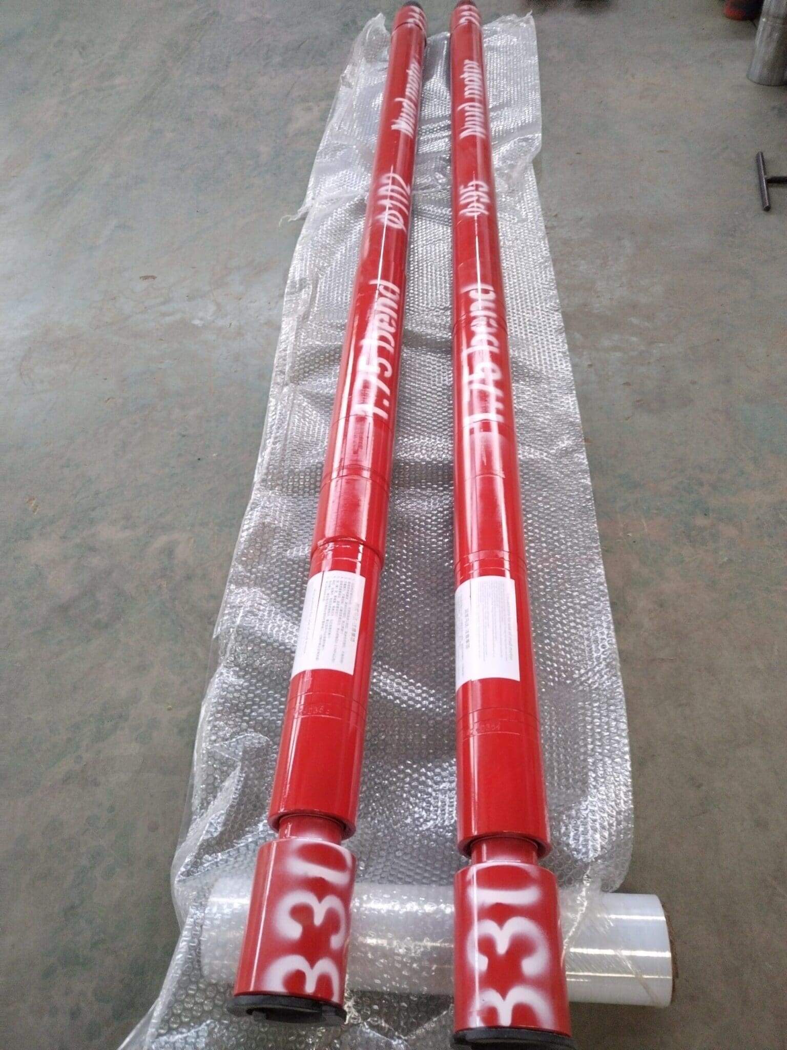
Where Galip fits
Galip builds mud motor test benches and runs every drilling mud motor we manufacture or repair across the bench before it leaves Pingyuan. The enclosed test cell in the photo at the top was built for a customer in the offshore services sector, sized for their motor range, with the loading, instrumentation, and reporting set up to their acceptance procedure. If you’re setting up mud motor testing in your own workshop, or you want your next motors delivered with a bench report your QA people can actually use, send us your motor sizes, flow range, and torque range and we’ll spec the bench, or the motors, around your program.
Planning motor testing for your shop?
Send your motor OD range, flow range, torque range, and how you want results reported. Send your requirements or write to sales@galipequipment.com.
Related reading: drilling motor dynamometer testing, the test stand acceptance procedure, mud motor rotors and stators, and the breakout unit we build for mud motor repair shops. Browse more technical guides.
Expert Consultation
Need more information on optimizing your equipment performance? Our engineering team is available for technical consultations.
Request a Quote
Tell us about your requirements and our engineering team will prepare a detailed proposal with specifications, pricing, and delivery timeline.
