
Mud Motor Stator and Rotor: Lobes, Fit and Failure Modes
7 essential insights into stator and rotor design in drilling mud motors. Power section mechanics, common failure modes, and performance optimization tips.
Find our product
The drilling industry has been revolutionized by drilling mud motors. They provide greater efficiency and better control in directional and horizontal operations. The stator and rotor are two of the most important components in these drilling mud motors. Together, these two components form the drilling mud motors’ power section. This article explores seven key insights into these components and their role in drilling operations.
1. What are Stators and Rotors?
Stator Derived by the word “static”, the stator is a stationary component of the drilling mud motor. It is usually made of an elastomeric material (rubber-like) with a spiral or helical shape. Its unique geometry is critical to its function as it determines how many lobes there are and how the fluid flows.
The power section is only part of the tool, and our guide to the other motor sections and how they fail covers the transmission, bearing assembly and bit sub that sit below it.
Rotor As the name implies, the rotor rotates within the stator. It is usually made from steel and has a helical form. The stator has one more lobe than the rotor, so the rotor will have discrete pockets or cavities that rotate with rotation.
2. Differential Pressure and its Power
Differential pressure is the basis for the operation of the drilling mud motors. These drilling mud motors are inflated when drilling fluid or mud is pumped through the drill string. This pressure is converted into rotational movement by the stator-rotor geometry.
3. Stator Design Variations
Stators are available in a variety of elastomeric material options, depending on the drilling environment.
- Nitrile Stators: Ideal when using water-based muds because of their resistance to absorption.
- Stators HNBR: Ideal for applications at higher temperatures and with better wear resistance.
- Fluoroelastomer (FEPM) Stators: Ideal for oil-based muds, and has exceptional resistance to harsh chemical agents.
4. Rotor materials and hard-facing
Although rotors are primarily steel, they may undergo processes such as chrome plating or hard-facing with tungsten carbide to increase their durability. These treatments are vital, as they:
- Reduce Wear Hard-facing reduces wear between the stator and rotor. This ensures longevity.
- Prevent corrosion: A protective layer on the rotor helps it resist corrosion in difficult drilling environments.
5. Evolutions of Lobe Design
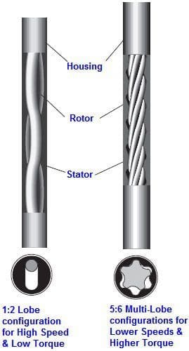
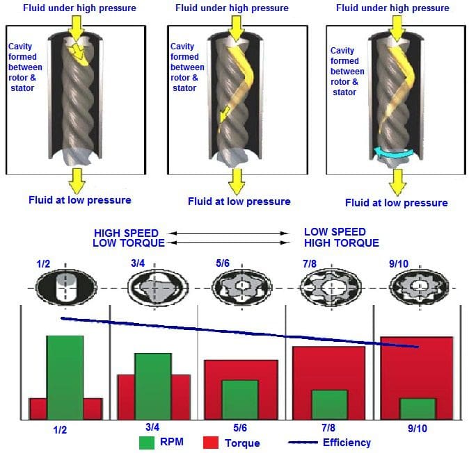
The lobes of the stator and rotor are fundamental to determining the drilling mud motors’ torque and speed. Most drilling mud motors have traditionally used a 1-lobe rotor turning inside a 2-lobe stator (a 1:2 configuration). The technology has advanced to allow for a variety of lobe combinations.
- 3/4 designs A balance between speed and torque.
- 5/6 and 7/8 designs: Higher torque at reduced rotational speed, ideal for hard rock drilling.
6. Design and Manufacturing Challenges
It is not easy to create the perfect stator or rotor. Engineers and designers should consider:
- Thermal expansion: Both parts expand when heated. The rotor will remain efficient even at high temperatures if the design is good.
- Wear and tear: The constant interaction between the stator rotor will cause wear. Materials and designs should be designed to minimize friction.
- Chemical Resistant: The stator elastomer must be able to resist chemical reactions with different mud compositions.
7. Maintenance
Periodic inspection of the stator & rotor will ensure long-lasting service life.
- Cleaning: Make sure no debris or mud remains after drilling as these can cause premature wear.
- Inspection Inspect regularly for signs of wear, cracks or abrasion. If necessary, replace the components.
- Storage: Store the drilling mud motor in a dry, clean place. Rotate the elastomer stator periodically to avoid it setting in one position.
Conclusion
The stators and rotors of drilling mud motors are engineering marvels. Their synergy powers the horizontal directional drilling operations which help us tap the Earth’s resources. Understanding the design, function and maintenance of these components is essential to ensuring the longevity of equipment as well as the efficiency of drilling operations. It’s exciting to see what new innovations will be made for these basic components as technology continues to advance.
the motors we build and the power sections in them
Related: worn rotors and stators show up clearly under load — here is how a mud motor test bench catches them.
Lobe configuration: what the ratio actually buys you
The rotor and stator lobe counts are the single biggest decision in the power section, because they set the trade between speed and torque before anything else is chosen. The stator always carries one more lobe than the rotor, and that extra lobe is what forms the sealed cavities the fluid pushes through.
| Rotor:stator lobes | Speed | Torque | Typically used for |
|---|---|---|---|
| 1:2 | Highest | Lowest | Small holes, high rpm work, some HDD applications |
| 4:5 | High | Moderate | General directional work where rate of penetration matters |
| 5:6 | Moderate | High | The common all-round choice for larger holes |
| 7:8 and above | Lowest | Highest | Hard formation, large bits, high weight on bit |
The pattern is consistent: more lobes means more cavities per revolution, so the output shaft turns more slowly and delivers more torque for the same flow. Fewer lobes reverses it. A mud motor stator with a low lobe count is not a cheaper version of a high lobe count one, it is a different tool for a different job.
Stage count is the second lever. A stage is one full helical pitch of the stator, and adding stages raises the differential pressure the power section can carry before it stalls. More stages means more torque available from the same lobe geometry, at the cost of a longer tool.
Rotor and stator fit, and why it decides tool life
The rotor is deliberately larger than the cavity it turns in. That interference is what seals the cavities, and it is the number that separates a motor that lasts a run from one that comes back chunked.
| Fit condition | What happens downhole | What you see on the tool |
|---|---|---|
| Too tight | High starting torque, elastomer works harder, heat builds inside the rubber | Chunked or torn elastomer, sometimes debonding from the tube |
| Correct for the temperature | Cavities seal, differential pressure translates to torque efficiently | Even wear across the profile |
| Too loose | Fluid slips past the seal, output falls, pressure signal goes soft | Polished lobe crests, low torque with normal flow |
Fit is chosen against the hole, not in isolation. Elastomer swells in hot holes and in oil-based fluids with a low aniline point, so a fit that is correct at surface can become too tight at depth. Fits are therefore specified against the expected bottomhole temperature and the mud system, which is why the same motor is supplied with different rotor sizes.
The stator itself comes in two constructions. A conventional stator has a thick rubber section at the lobe roots and a thin one at the crests. An even-wall stator carries a uniform rubber thickness on a profiled steel tube, which sheds heat better and tolerates higher differential pressure. The even-wall design costs more and is usually specified where temperature or duty is severe.
How a power section fails, and what each failure looks like
| Failure | Cause | How it shows at surface |
|---|---|---|
| Chunking | Repeated stalling, or a fit too tight for the temperature | Torque falls away, pressure signal becomes erratic |
| Debonding | Heat at the rubber-to-steel bond, or chemical attack | Sudden loss of output, sometimes rubber recovered at surface |
| Swelling | Fluid incompatible with the elastomer | Rising differential pressure for the same weight on bit |
| Rotor coating loss | Abrasive solids, or corrosion attacking the chrome | Gradual output decline across several runs |
| Hysteresis heating | Rubber flexing faster than it can shed heat | Short run life in hot holes with no other symptom |
Stalling is the common thread. When applied differential exceeds what the power section can hold, the rotor stops while the pumps keep pushing, and the elastomer takes a load it was never designed to carry. One stall rarely destroys a motor. A run full of them usually does, and the evidence arrives as chunks in the shaker rather than as a warning downhole.
Most of this is measurable before the tool goes in the hole. A bench run records output against differential pressure and gives a curve you can compare against the last one for the same motor, which turns a subjective judgement about a used power section into a documented one.
Related detail sits in the sibling articles: rotor and stator fit in more depth, how nozzle sizing decides the pressure the power section gets, and the bearing assembly below it.
Expert Consultation
Need more information on optimizing your equipment performance? Our engineering team is available for technical consultations.
Request a Quote
Tell us about your requirements and our engineering team will prepare a detailed proposal with specifications, pricing, and delivery timeline.
