
Mud Motor Nozzle Sizing: Balancing Motor and Bit Pressure
How to split a fixed standpipe pressure budget between a mud motor and the bit nozzles, with worked TFA numbers and the bearing-flow deduction most calculations miss.
Mud motor nozzle sizing splits one fixed surface pressure budget between the motor and the bit. The motor claims its differential pressure first, and whatever is left over pays for bit hydraulics. Hydraulics sit outside the IADC roller cone code entirely, which is why nozzle sizing has to be settled separately from bit selection. Opening the nozzles protects motor headroom and reduces stalling. Tightening them buys jet impact at the bit, but only when the pumps have pressure to spare.
At a glance
| Question | Short answer |
|---|---|
| What sets the ceiling? | Pump pressure rating, or the rig’s working pressure limit — whichever is lower |
| Who gets paid first? | The motor. Its differential pressure rises with weight on bit and is not optional |
| What does the bit get? | Whatever remains after surface losses, string losses, motor pressure and annulus losses |
| Usual mistake | Carrying rotary-run nozzles into a motor run and losing the pressure headroom |
| Direction of the fix | Larger total flow area (TFA), meaning fewer restrictions and lower bit pressure drop |
| What it costs you | Jet impact and hydraulic horsepower per square inch at the bit face |
Where the pressure actually goes
Standpipe pressure is not a single number produced by the bit. It is the sum of every restriction between the pump discharge and the flowline, and the bit is only one of them. Written out, the budget looks like this:
- Surface equipment: standpipe, hose, swivel, kelly or top drive
- Drill string bore, all the way down
- The motor: its own no-load loss, plus the working differential pressure it develops under load
- The bit nozzles
- The annulus, back to surface
Four of those five are fixed once the string is made up. Nozzles are the one term the shop can still change while the bit is on the bench, which is why motor runs live or die on that choice.
A positive displacement motor produces torque in proportion to the pressure drop across its power section. Push harder on bottom and the rotor resists more, the pressure across the rotor and stator climbs, and standpipe pressure climbs with it. That rise is the driller’s torque gauge. It is also the reason the motor cannot be treated as a fixed restriction: it takes more pressure exactly when the well is asking the most of it.
The three numbers you need before you pick nozzles
| Number | Where it comes from | What it decides |
|---|---|---|
| Maximum allowable standpipe pressure | Pump rating, relief valve setting, or rig working pressure (take the lowest) | The size of the whole budget |
| Motor maximum differential pressure | Motor data sheet, confirmed on a test bench | How much you must hold in reserve |
| Off-bottom circulating pressure | Measured on the rig, bit off bottom, motor turning free | Your zero point for reading differential |
The third one is the number crews skip, and it is the only one measured on the actual string in the actual hole. Circulate off bottom at the flow rate you intend to drill with, record the standpipe pressure, and write it on the tour sheet. Every differential reading for the rest of the run is that baseline subtracted from the live gauge. Without it, the driller is guessing at motor load from an absolute pressure that includes several hundred psi of things that have nothing to do with the motor.
Working a real example
Total flow area is the sum of the nozzle throats. For nozzles sized in thirty-seconds of an inch, one nozzle contributes π/4 × (d/32)² square inches. Three 12/32 in. nozzles come to 0.331 in². Three 14/32 in. nozzles come to 0.451 in².
Bit pressure drop follows the standard field relationship, with mud weight in lb/gal, flow in gal/min and area in in²:
ΔP(bit) = (MW × Q²) ÷ (12,042 × Cd² × TFA²) Cd ≈ 0.95
Take 300 gal/min of 9.5 lb/gal mud. On three 12/32 nozzles the bit takes about 718 psi. Open the same bit to three 14/32 nozzles and it takes about 387 psi. Two nozzle sizes released roughly 330 psi, and that 330 psi is now available for the motor to use as weight goes on. This is the whole of mud motor nozzle sizing in one comparison: you are not tuning the bit, you are deciding how much room the motor is allowed.
The cost is visible in the same arithmetic. Hydraulic horsepower at the bit is ΔP × Q ÷ 1,714, so the 12/32 case delivers about 126 hydraulic horsepower against about 68 for the 14/32 case. Spread over an 8½ in. bit face of 56.7 in², that is roughly 2.2 against 1.2 horsepower per square inch. Cleaning ability at the cutting structure very nearly halved.
What the bearing pack takes before the bit sees anything
A detail that rarely reaches the nozzle calculation: on a mud-lubricated motor, part of the flow never reaches the nozzles at all. A share of it is bled through the bearing assembly to cool and lubricate the races, rejoining the stream below. Commonly quoted figures sit somewhere between four and ten per cent, and the motor’s own documentation is the place to confirm it for a given design.
Run the example again with eight per cent diverted. The nozzles now see 276 gal/min rather than 300. On the 12/32 dressing, the bit drop falls from about 718 psi to about 608 psi. That is helpful for the pressure budget and unhelpful for hole cleaning, and either way it means the figure you calculated from pump output was never the figure at the bit. An oil-sealed motor does not have this problem, because nothing is diverted — one more reason the sealed-versus-lubricated choice reaches further than bearing life.
When to open the nozzles up
| Situation | Why it squeezes the budget | Practical response |
|---|---|---|
| Long horizontal or extended-reach section | String and annulus losses grow with every joint | Increase TFA before the section, not halfway through it |
| Heavy mud weight | Bit drop scales directly with mud weight | Recalculate at the planned weight, not the current one |
| High-torque bit, hard formation | The motor needs more differential to hold the same rate of penetration | Reserve headroom equal to the motor’s rated maximum differential |
| HDD rig with a modest pump | The pressure ceiling is low to start with | Size for the ceiling first; see HDD motor sizing |
| Repeated stalling on the last run | Differential is already reaching the motor’s limit | Open TFA and reduce weight on bit together |
Stalling is the failure this protects against. When applied differential passes what the power section can hold, the rotor stops turning while the pumps keep pushing. Pressure spikes, the elastomer is loaded in a way it was never meant to carry, and repeated events tear chunks out of the stator lining. A motor pulled with a chunked stator has usually been stalled, not worn out.
Flow rate and nozzle size move together
There are two ways to lower bit pressure drop: open the nozzles, or pump less. The second looks like the easier lever and it is the more expensive one, because flow rate is doing three jobs at once. It sets motor speed, it sets annular velocity for hole cleaning, and only then does it set bit drop.
| Check | Sets the floor because | Consequence of ignoring it |
|---|---|---|
| Motor recommended flow window | Below the window the power section cannot develop rated output | Slow drilling that looks like a bit problem |
| Annular velocity in the largest open hole | Cuttings have to be carried, not stirred | Packed-off annulus, rising standpipe pressure, stuck pipe risk |
| Bit face cleaning at the planned weight | Cuttings regrind if jets cannot clear the cutting structure | Falling penetration rate with no pressure symptom |
Because those floors are set by the well rather than by the tool, flow rate is usually decided first and stays fixed. That leaves nozzle area as the adjustable term, which is why mud motor nozzle sizing ends up carrying the whole balance. Where the calculation refuses to close at any nozzle size, the honest reading is that the motor, the bit or the pump is the wrong one for the section.
One more practical point on sequencing. Do the sums before the bit leaves the shop, because nozzles are a bench job and a bit trip is not. Crews that treat mud motor nozzle sizing as something to sort out on the rig floor end up choosing between drilling with the wrong hydraulics and pulling out to fix it.
When nozzle sizing is not the deciding factor
Plenty of poor motor runs get blamed on the bit dressing when the cause was somewhere else entirely. Before changing nozzles, rule these out:
| Observation | More likely cause | What to check first |
|---|---|---|
| Standpipe pressure erratic from the first circulation | Washed string, leaking sub, or a stuck bypass valve | Pressure-test the string before touching the bit |
| Motor turns but produces little torque | Worn rotor and stator fit, or a stator swollen by the mud system | Bench test before the next run |
| Flow rate below the motor’s stated range | Under-pumping, not over-nozzling | Confirm the motor’s recommended flow window |
| Pressure normal, rate of penetration poor | Bit selection or formation, not hydraulics | Compare the bit type against the offset record |
| Vibration and irregular torque | Bottomhole assembly dynamics or a worn transmission | Inspect the drive line at the next service |
Opening the nozzles on a motor that is failing for a mechanical reason simply hides the symptom for one more run. The pressure signature flattens, the driller loses the early warning, and the tool comes back in worse condition than it would have done.
Reference: nozzle areas and what they cost
| Dressing | TFA (in²) | Bit drop at 300 gpm, 9.5 ppg |
|---|---|---|
| 3 × 10/32 | 0.230 | ≈ 1,486 psi |
| 3 × 11/32 | 0.278 | ≈ 1,017 psi |
| 3 × 12/32 | 0.331 | ≈ 718 psi |
| 3 × 13/32 | 0.389 | ≈ 520 psi |
| 3 × 14/32 | 0.451 | ≈ 387 psi |
| 3 × 16/32 | 0.589 | ≈ 227 psi |
Read the right-hand column as a price list. Every step up in nozzle size hands pressure back to the motor and takes it away from the bit face. There is no setting that gives both, which is why the decision belongs to whoever knows what the section is going to demand.
Selection checklist before you dress the bit
- Write down the pressure ceiling — the lowest of pump rating, relief setting and rig limit.
- Subtract the motor’s rated maximum differential pressure. That block is spoken for.
- Subtract estimated surface, string and annulus losses at the planned flow rate and mud weight.
- Deduct the bearing-pack diversion if the motor is mud-lubricated, and recalculate flow at the nozzles.
- Size TFA so the bit drop fits inside what is left, with margin rather than exactly.
- Check the resulting horsepower per square inch against the offset wells. If it is too low to clean the hole, the answer is a larger motor or a different flow rate, not smaller nozzles.
- Record the off-bottom circulating pressure on the first circulation and post it where the driller can see it.
Step six is the one that keeps this honest. Sound mud motor nozzle sizing sometimes concludes that the tool selection was wrong, and no nozzle set will rescue it.
Proof and documentation
The differential pressure figure on a data sheet is a design value. What a motor actually costs you in pressure at a given flow rate is a measured value, and the two are not always the same once a tool has been through a few runs and a rebuild or two. A test bench settles it: circulate at the intended rate, record the loss with the motor turning free, then load it and record the differential against torque. That gives the two numbers this whole calculation rests on, taken from the tool being shipped rather than the family it belongs to.
Ask for that record with the motor. A performance curve and a witnessed no-load pressure reading turn mud motor nozzle sizing from an estimate into arithmetic, and they cost nothing at the point of manufacture. Galip’s motors are built and finished in-house, and the process is described on the motor manufacturing page, and bench records travel with the tool.
For general drilling hydraulics practice, the International Association of Drilling Contractors publishes reference material used widely across the industry.
Frequently asked questions
Should motor runs always use bigger nozzles than rotary runs?
Usually, yes. A rotary run has no downhole tool claiming several hundred psi, so more of the budget can go to the bit. Carrying that same dressing onto a motor run is the most common way crews end up with no headroom left when weight goes on.
How do I read motor differential pressure at surface?
Subtract the off-bottom circulating pressure from the live standpipe pressure at the same flow rate. The difference is what the motor is developing. Both readings have to be taken at the same rate, or the comparison is meaningless.
Can I blank off one nozzle instead of changing all three?
You can, and it moves TFA in the wrong direction for a motor run. Blanking a nozzle reduces total flow area and raises bit pressure drop, so it takes headroom away from the motor rather than giving it back.
What happens if the flow rate is below the motor’s range?
Output torque and speed both fall away, and no nozzle change corrects it. Each motor size carries a recommended flow window; below it the tool underperforms, above it stator wear accelerates. Fix the rate first, then size the nozzles around it.
Does mud weight change the nozzle choice?
Directly. Bit pressure drop is proportional to mud weight, so the same nozzles cost noticeably more pressure in a heavy system. Recalculate for the weight the section will be drilled at rather than the weight in the pits today.
How much margin should I leave above the motor’s rated differential?
Enough that a normal weight-on-bit excursion does not reach the limit. Working right at the rating leaves nothing for the moment the bit takes a hard stringer, which is exactly when stalls happen.
Does a sealed-bearing motor change the calculation?
It removes one step. Nothing is diverted for bearing lubrication, so the flow at the nozzles equals the flow down the string. On a mud-lubricated tool you have to deduct the bearing share before the bit drop is calculated.
Is there a quick sanity check on a nozzle choice?
Add the calculated bit drop to the motor’s rated maximum differential and to your estimated circulating losses. If that total sits close to the pressure ceiling, the nozzles are too small. A sound result leaves visible daylight, because the well will use some of it.
Getting a motor specified
Nozzle choice is downstream of tool selection, and a motor matched to the section removes most of the argument. If you are specifying one, send the job envelope rather than a model number:
- Hole size and bit type
- Planned flow rate and mud weight, and the pressure ceiling on the rig
- Formation and expected torque demand
- Bearing preference, sealed or mud-lubricated, and why
- Connection family top and bottom
- Daily running hours and expected service interval
- Report format you need with the tool: performance curve, no-load pressure, inspection record
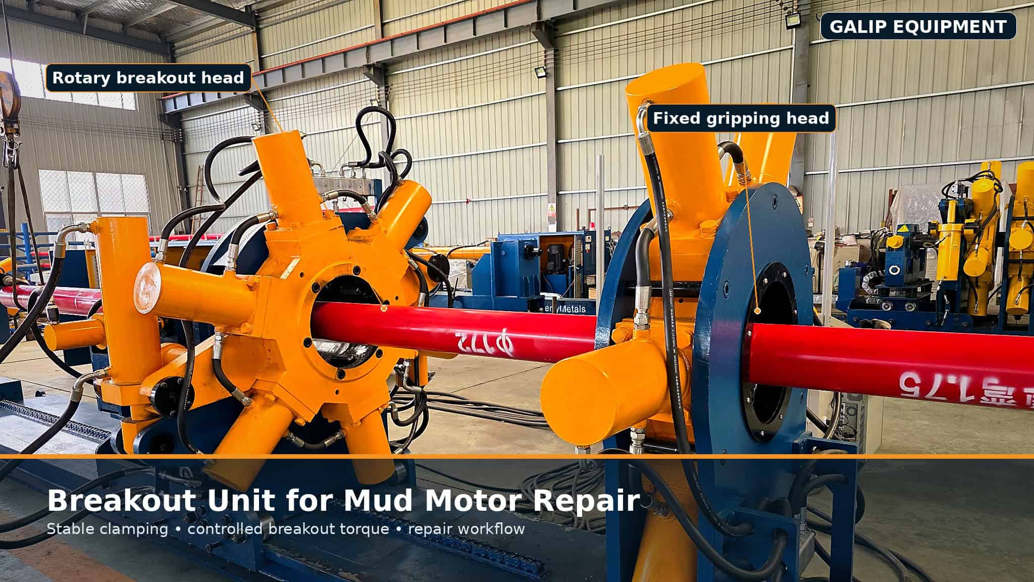
Shops running their own repairs should also look at what the workshop needs to support the tool: the breakout equipment for opening the connections without damaging them.
Short checklist
- Pressure ceiling written down before anything else
- Motor rated differential reserved, with margin
- Bearing-pack diversion deducted on mud-lubricated tools
- TFA sized from the remainder, at planned mud weight
- Horsepower per square inch checked against offsets
- Off-bottom circulating pressure measured and posted on the first circulation
- Bench record for the specific tool held on file
Expert Consultation
Need more information on optimizing your equipment performance? Our engineering team is available for technical consultations.
Request a Quote
Tell us about your requirements and our engineering team will prepare a detailed proposal with specifications, pricing, and delivery timeline.
