
Drilling Stabilizer Guide: Gauge, Blades, Wear and Rebuilds
Learn how to specify a drilling stabilizer by gauge, blade geometry, junk slot area and hardfacing, then inspect wear and decide when to rebuild.
A drilling stabilizer is a short sub with raised blades that hold the drill string centred in the hole. It does two jobs at once: it controls where the string touches the wall, which is what sets directional behaviour, and it keeps the collars off the wall, which reduces the risk of the string sticking. For where the stabilizer sits in the whole string, see drill string components.
Article contents
Drilling stabilizer at a glance
| Question | Short answer |
|---|---|
| What does it do? | Centralises the string and sets where it contacts the hole |
| Main construction types | Integral blade, welded blade, and replaceable sleeve |
| Straight or spiral blades? | Spiral covers the full circumference over the tool length; straight contacts three fixed lines |
| What is gauge? | The diameter measured across the blades, nominally the hole size |
| What limits blade count? | Junk slot area. More blades means less room for cuttings |
| What condemns one? | Cracks at the blade roots, body OD below the inspection minimum, or too little metal left to recut |
Drilling stabilizer construction types
Construction decides how strong it is, what it costs, and what happens when the blades wear out.
| Type | How it is made | Trade-off |
|---|---|---|
| Integral blade | Blades machined from one forged bar, so body and blades are a single piece | Strongest and the usual choice for drilling. Rebuilt by welding up and re-dressing |
| Welded blade | Blades welded onto a body | Cheaper, and the weld is the weak point. Kept away from high-torque and critical work |
| Replaceable sleeve | A bladed sleeve keyed or screwed onto a mandrel | Change the sleeve at the rig instead of pulling the sub. More parts to come loose |
A fourth variant is the non-rotating sleeve, where a rubber or polymer sleeve stays put against the wall while the mandrel turns inside it. Because the sleeve is not rubbing as it rotates, it cuts torque and drag and is gentler on whatever it bears against, in casing or in open hole. It is a torque-and-drag tool, and directional work is not what it is for.
Drilling stabilizer blade geometry
Two things describe the blades: how they run along the body, and how many there are.
| Geometry | What it does | Where it suits |
|---|---|---|
| Straight blades | Run parallel to the axis, contacting the same three azimuths for the whole run | Simple, and acceptable where hole quality is good |
| Spiral blades | Wrap helically, so the contact sweeps the full circumference over the length of the tool | The general-purpose choice, and better through soft or washed sections |
| Three blades | Three points positively centre the tool, with the widest gaps | The standard arrangement, and the most flow area |
| Four or more blades | More bearing area, so contact load is spread wider | Harder formations and heavier loads, at the cost of flow area |
The spiral is worth understanding properly, because it is often explained wrongly. At any single cross-section a three-blade spiral still touches at three points, exactly like a straight-bladed tool. What changes is coverage along the length: as the blades wrap, the contact moves round the hole, so no axial strip of wall is left untouched and the bearing load is spread around the circumference instead of concentrated on three fixed lines.
That gives a number to specify against. For the contact to close up over the tool length, each blade needs to wrap at least 360 degrees divided by the blade count, so roughly 120 degrees per blade on a three-blade tool and 90 on a four. Blade width helps a little, so slightly less will do in practice. Well below that figure and the wrap is decorative: the gaps stay open, and in soft rock the blades cut grooves and let the string move.
Junk slot area and hole cleaning
The gap between blades is the flow path for everything the bit has just cut, and it is called the junk slot area.
Adding blades to get steadier support takes that area away. Widening blades to spread the contact load takes it away again. Get it wrong and cuttings pack around the tool, the annulus blocks, standpipe pressure climbs, and what began as a stability decision becomes a stuck pipe problem.
| Situation | Which way to lean |
|---|---|
| Large hole, high rate of penetration, plenty of cuttings | Fewer, narrower blades to keep the slots open |
| Hard formation, low penetration rate | More blade contact is affordable, since there is less to carry away |
| Soft or unconsolidated formation | Spiral blades, and watch for blades cutting into the wall |
| Known hole cleaning problems | Treat junk slot area as the governing number, ahead of stability |
Why drilling stabilizer gauge controls performance
Gauge is the diameter measured across the blades, and it is nominally the hole size. Everything a drilling stabilizer is supposed to do assumes it is touching the wall, so gauge is the one measurement that has to be right.
Because gauge is a diameter, a tool 1/8 in under gauge lets the string sit 1/16 in off centre, half the deficit. That sounds small. It is enough to soften a directional tendency measurably, and the loss is progressive: the tool does not stop working at a threshold, it degrades from the first thousandth.
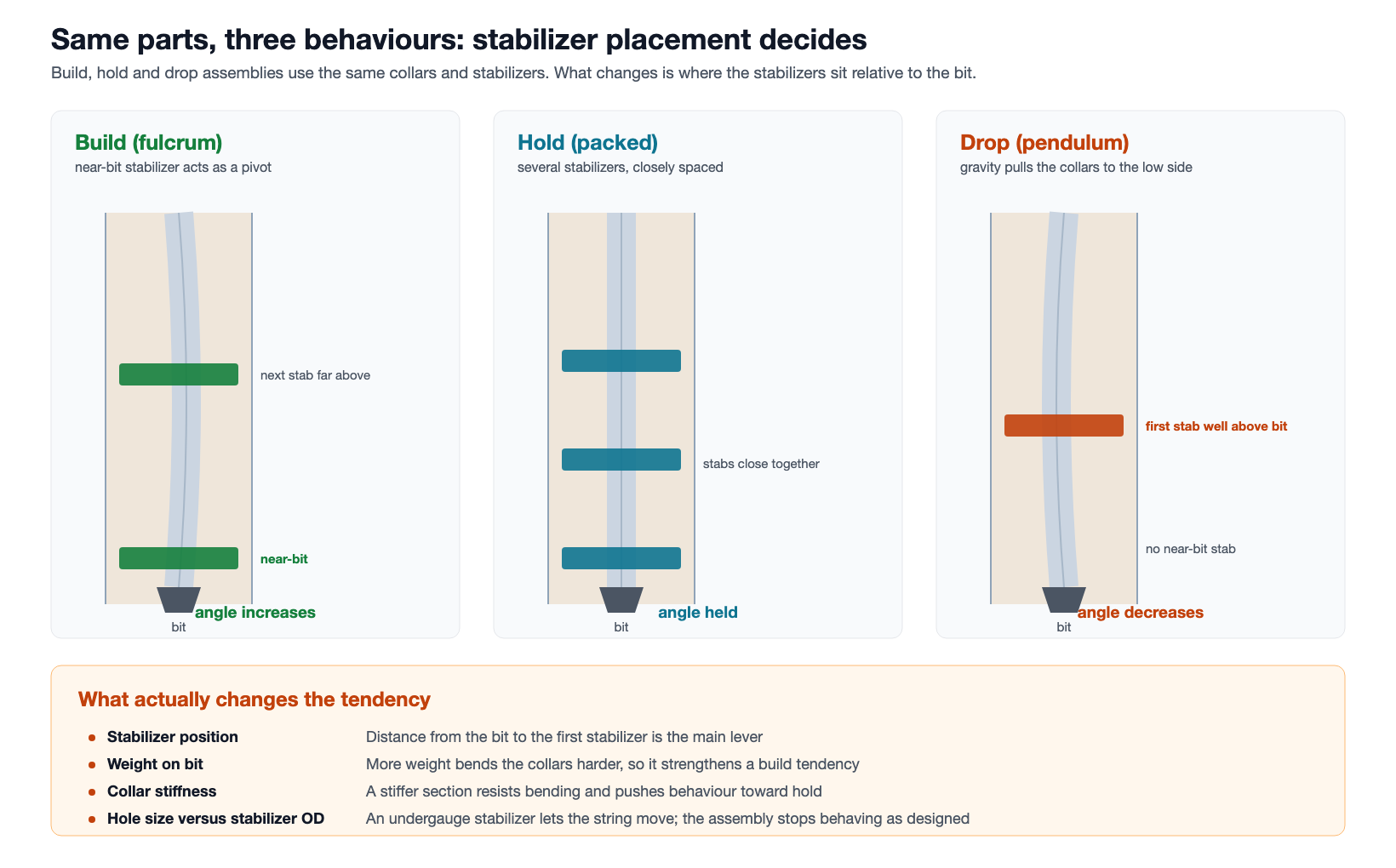
Check it with a ring gauge before the string goes in, record the reading with the date, and reject against the figure in your inspection specification or the operator’s drilling programme. Where the tool then sits in the string, and what that placement does to hole angle, is covered in the guide to build, hold and drop assemblies.
Designed undergauge versus worn undergauge
A drilling stabilizer can be specified slightly under hole size on purpose, to soften a tendency, to ease running through a tight section, or to reduce the contact that invites sticking. That is a deliberate choice made when the assembly is designed, and it is written down.
A tool that has worn under gauge is a different situation entirely. Nobody chose the number, it is not recorded anywhere, and it drifted while the tool was in the hole. The assembly is now behaving to a dimension the directional plan never accounted for. When someone says a stabilizer is undergauge, ask which of the two they mean.
A drilling stabilizer is not a reamer
These two get ordered interchangeably and they should not be. Both sit in the assembly, both are roughly hole size, and both touch the wall, which is where the resemblance stops.
| Tool | What it is for | How it acts on the wall |
|---|---|---|
| Drilling stabilizer | Centralise the string and set contact points | Bears against the wall, and is not designed to cut |
| Roller reamer | Hold the hole at gauge in abrasive or hard formation | Rotating cutters work the wall as the string turns |
| Hole opener | Enlarge the hole beyond the size the bit drilled | Cuts, by design and substantially |
A roller reamer does stabilise as a side effect, which is why the confusion survives. But specifying a reamer where a stabilizer belongs adds cutting structure, cost and failure modes you did not need, and specifying a stabilizer where the hole is closing in means the tool wears out doing a job it was never dressed for.
Hardfacing choices for drilling stabilizer blades
Bare steel blades would wear out quickly, so the contact faces carry a wear-resistant layer. The choice depends on what the tool will rub against.
| Dressing | Character | Suits |
|---|---|---|
| Pressed-in tungsten carbide inserts | Individual buttons set into the blade face | Abrasive open hole, where long life matters most |
| Crushed or granular carbide in a matrix | A continuous hard layer | General open-hole work, and easy to reapply |
| Casing-friendly overlay | Hard enough to resist wear, chosen not to cut casing | Anything that will rotate inside casing |
| Bare or lightly dressed | No meaningful wear protection | Short runs in soft formation only |
Aggressive carbide holds gauge beautifully in open hole and cuts grooves in casing on the way past. If any part of the run is inside casing, the dressing has to be chosen for that. State it on the order.
When a drilling stabilizer is not the answer
| Problem | More likely cause | Look here first |
|---|---|---|
| Hole angle not behaving | Placement or gauge, ahead of blade design | The gauge readings, then where the tool sits in the string |
| String still sticking after adding stabilizers | Overbalance against a permeable zone, which more blades will not cure | Mud weight and total contact area, including whether spiral collars would help |
| Pressure climbing while drilling | Cuttings packing, often around a tool with too little slot area | Flow rate and annular velocity before the assembly |
| Vibration and irregular torque | Assembly dynamics or bit selection | Drilling parameters, then the string design |
| Casing wear | Hardfacing chosen for open hole and run inside casing | What the blades are dressed with |
Drilling stabilizer wear, rebuilding and rejection
Blades are consumable. A tool worn under gauge is normally a rebuild: the blades are welded up, re-dressed to gauge and re-hardfaced, or on a sleeve design the sleeve is replaced. That is routine shop work.
Connections are usually recoverable too. A galled or washed connection is normally recut and refaced, subject to enough parallel body length and enough material left to do it, which is exactly why bench-mark and minimum-length dimensions exist in the inspection specs. What actually condemns a tool is body damage: cracks, typically at the blade roots or the last engaged thread, body OD worn below the minimum in the specification, or too little metal remaining to recut the connection again.
- Check gauge with a ring gauge. On a three- or five-blade tool there are no opposed blades to caliper across.
- Take the check at several points along the blade length and note where it is tightest, since wear is rarely even along the tool or around it.
- Inspect the connections at the same interval as the collars they run with.
- Look at the blade roots for cracking, which is the condemning defect rather than a rebuildable one.
- Record how many times the tool has been rebuilt, because that is what predicts the next one.
How to read uneven drilling stabilizer wear
Uneven wear carries information, but it has to be read carefully, and the obvious reading is usually the wrong one. A rotating stabilizer presents every blade to the loaded side of the hole once per revolution, so a string lying on the low side normally wears the blades evenly. Side load is not what singles out one blade.
| What you see | What it points at |
|---|---|
| All blades worn evenly | Normal rotating service, or high side load with the string turning |
| One blade worn, the others near new | The tool was not turning relative to the wall while loaded: sliding with a motor, a seized non-rotating sleeve, or the string held stationary while being worked |
| Chipped or battered leading edges | Whirl, or impact damage from back-reaming through ledges |
| Blades that differ from new, with no run to explain it | Inconsistent hardfacing at the last rebuild |
Each of those sends you somewhere different, so record which pattern you actually saw rather than a verdict. Keep the readings as numbers with dates. Three measurements across three runs give you a wear rate, and a wear rate is what tells you whether the tool will survive the next section. The same argument applies to the pipe these tools run with, which is why inspection classes are defined as measured bands rather than a stamp.
Workshop handling and breakout
A stabilizer is an awkward thing to put on a bench. It is short and heavy, and the raised blades defeat a set of pipe jaws.
The blades themselves are the problem. Clamping across them concentrates load on the hard-dressed faces, which is both bad for the tool and unreliable as a grip. Clamping on the body between blades needs a jaw arrangement sized for the body, not for the diameter across the blades, and the two are far apart: a stabilizer dressed to 8-1/2 in gauge may sit on a 6-1/2 in body, so the jaws have to close two inches smaller than the number on the tool ticket.
There is also not much parallel body between the blades and the connection, and what there is has to carry the full break-out torque of a collar-sized connection. A machine that handles long drill pipe comfortably can find a stabilizer awkward for exactly that reason: the load is high and the surface available to take it is short. Send both diameters on the enquiry, or you will be quoted a machine sized to the wrong one. The specification side is on the make-up and break-out equipment page.
- Break-out capacity with real margin over the recommended make-up torque of the largest connection you handle. Connections come out of the hole over-torqued by downhole rotation, so sizing on the make-up figure alone leaves the machine stalling on the jobs it was bought for.
- How the hard-dressed faces will be protected from the jaws, and the marking limit your customers accept.
Drilling stabilizer ordering checklist
- Hole size, which sets the gauge diameter
- Body outside diameter, given separately from the gauge diameter, so the shop can grip it
- Construction: integral blade, welded, or replaceable sleeve, with a reason for the choice
- Blade geometry and count, decided against junk slot area as well as stability
- Wrap angle per blade, if you are specifying spiral
- Hardfacing, and explicitly whether any part of the run is inside casing
- Connection designation at both ends, given as an NC or REG number
- Fishing neck dimensions, if the tool has one
- Rebuild history, if the tool is not new
Drilling stabilizer questions
What does a drilling stabilizer do?
It centralises the drill string in the hole. That controls where the string touches the wall, which sets how the assembly builds, holds or drops angle, and it keeps the collars off the wall so they are less likely to stick.
What is the difference between integral blade and sleeve stabilizers?
An integral blade tool is machined from one piece, so the blades and body are the same forging. A sleeve type carries the blades on a separate sleeve fitted to a mandrel, so the worn part can be swapped without pulling the whole sub.
Are spiral blades better than straight?
For most work, yes, though not for the reason usually given. At any one cross-section a spiral tool still contacts at three points. The gain is over the tool’s length: the wrap sweeps the contact around the hole, so the load is spread circumferentially instead of bearing on three fixed lines that can groove a soft wall.
How much wrap does a spiral blade need?
At least 360 degrees divided by the blade count for the coverage to close up, so about 120 degrees per blade on a three-blade tool and 90 on a four. Blade width buys back a little, but well under that and the wrap is cosmetic.
How far under gauge is too far?
Work to the figure in your inspection specification or the operator’s programme rather than a rule of thumb, and record the measured number. Remember gauge is a diameter, so the string moves off centre by half the deficit.
What is junk slot area?
The open flow area between the blades. Cuttings pass through it, so adding blades or widening them for stability reduces the room available for hole cleaning.
Can a worn stabilizer be repaired?
Usually. Blades are welded up, re-dressed to gauge and re-hardfaced, or the sleeve is replaced on a sleeve design, and a galled connection is normally recut and refaced. What ends a tool’s life is body damage: cracks at the blade roots, body OD below the inspection minimum, or too little metal left to recut again.
Will a stabilizer damage casing?
It can, if the hardfacing was chosen for abrasive open hole. Where any of the run is inside casing, specify a casing-friendly dressing and say so on the order.
What is the difference between a drilling stabilizer and a reamer?
A stabilizer bears against the wall to centralise the string and is not meant to cut. A roller reamer carries rotating cutters that work the wall to hold the hole at gauge in abrasive formation. A hole opener enlarges the hole beyond bit size.
How many blades should a drilling stabilizer have?
Three and four are both common. Decide it against junk slot area as well as support: more blades steady the string but leave less room for cuttings, which matters most in large hole and at high penetration rates.
Why do stabilizer blades wear unevenly?
Rarely from side load, since a rotating tool takes that on every blade once per revolution and wears evenly. One blade worn while the others look new means the tool was not turning relative to the wall while loaded, typically sliding with a motor or held stationary while the string was worked. Chipped leading edges suggest whirl, and blades that simply differ suggest inconsistent hardfacing at the last rebuild.
Expert Consultation
Need more information on optimizing your equipment performance? Our engineering team is available for technical consultations.
Request a Quote
Tell us about your requirements and our engineering team will prepare a detailed proposal with specifications, pricing, and delivery timeline.
