
Torque Monitoring for OCTG Pipes: A Practical QA Guide
How OCTG torque monitoring controls make-up, identifies abnormal joints, and builds traceable, audit-ready records — with a 9-point control framework and buyer checklist.
What torque monitoring for OCTG pipes actually means
OCTG – oil country tubular goods – includes casing, tubing, coupling stock, pup joints, and related products used in well construction and production. These products may use API connections, proprietary premium connections, or customer-specific assemblies. Although the mechanical act of make-up is familiar, the quality risk is not identical from one connection family to another.
Basic torque monitoring records the applied torque as the connection is assembled. A stronger system also records angular movement, commonly displayed as turns (see how to read a torque-turn graph), so the operator and QA team can review the path to the final condition. That is why the phrase torque-turn monitoring is often more useful than torque monitoring alone. Torque shows resistance. Turns show movement. Read together, they describe how the connection progressed.
A monitoring record is still not a substitute for thread inspection, correct compound, clean handling, alignment, or the official procedure. It is evidence about the operation. If the physical setup was wrong, the graph may simply document a bad process accurately. Effective monitoring therefore begins before rotation starts and continues after the report is saved.
A four-level maturity model for OCTG torque monitoring
A useful way to evaluate a workshop is to ask what level of evidence it can produce. The following four levels separate a simple torque indication from a complete quality-control system.
| Monitoring level | What is captured | Why it matters |
|---|---|---|
| Level 1: Final torque | The operator sees or records the finishing torque. | Fast and simple, but it says little about the make-up path or joint identity. |
| Level 2: Torque + turns | The system records a torque-turn curve for the event. | Abnormal movement, early resistance, spikes, or interrupted make-up become visible. |
| Level 3: Joint record | The curve is tied to the correct job, joint, procedure revision, operator, date, and exception status. | The result can be reviewed after shift change or during a customer audit. |
| Level 4: Batch intelligence | The workshop reviews trends across multiple similar joints or lots. | The team can detect drift in setup, compound practice, handling, or equipment condition before rejection rates rise. |
Many shops believe they have a torque-monitoring program because a digital torque value appears on a screen. In practice, the largest improvement usually comes when the shop moves from Level 2 to Level 3: the graph is no longer an isolated image; it becomes part of a traceable joint record. Level 4 then turns repeated work into a learning system rather than a series of unrelated jobs.
Why the same target torque can produce different results
Torque is influenced by friction and by the mechanical condition of the connection. Two nominally similar joints can reach the same finishing value through different paths. The reasons are usually found in the setup, the connection, or the operating method.
- Thread cleanliness and visible damage: contamination, corrosion, burrs, impact damage, or poor thread-protector discipline can change resistance early in the make-up.
- Thread compound: product selection, mixing, coverage, contamination, and application quantity all influence friction.
- Alignment and support: an off-center or poorly supported workpiece can create side loading and an abnormal torque rise.
- Rotation speed: rapid approach may hide useful detail, increase overshoot, or make the final region harder to control.
- Clamping stability: movement or slippage can create spikes, drops, or a saw-tooth pattern that weakens the record.
- Surface and material condition: CRA, chrome, coated, or otherwise damage-sensitive products require jaws and handling practices matched to the application.
- Connection family and product combination: size, weight, grade, pin/box combination, and mixed assemblies can change the approved make-up requirement.
- Environment and storage: temperature, moisture, dust, and long storage periods can affect compound condition, cleanliness, and handling discipline.
This is why a torque target should never be treated as a universal property of an outside diameter. The shop must verify the complete connection definition and use the latest official data for the actual product combination. TenarisHydril, for example, provides official OCTG product datasheets and a mixed-assembly torque calculator so users can select the correct product combination rather than relying on a generic shop chart.
Nine controls that make an OCTG torque record defensible
1. Control the source of the target value
The approved torque window, turn criteria, shoulder criteria, speed requirement, and compound instruction should come from a controlled source. Record the document title or revision used for the job. A handwritten value copied from an old board is not enough when the connection owner has issued a newer data sheet.
2. Identify the joint before make-up
The record should connect to the correct work order, customer, product description, joint or serial reference, and operation mode. Entering this information after the job increases the risk of attaching a good curve to the wrong connection.
3. Verify calibration status and system readiness
Operators do not need to perform a calibration before every joint, but they should know whether the measurement system is within its approved calibration interval and whether pre-use checks have passed. A believable graph produced by an overdue or suspect system is still weak evidence.
4. Confirm support, alignment, and clamp condition
Before rotation, verify center height, roller or support position, contact surfaces, jaw selection, clamp condition, and clear working space. The workpiece should sit naturally in the machine. The equipment should not be used to force a misaligned connection into position.
5. Control the approach
The operator should use the approved run-in method and control the transition into the higher-load region. A smooth, observable approach makes it easier to recognize unexpected resistance and reduces the chance of overshoot.
6. Review the curve, not only the endpoint
A final torque inside the target range does not automatically explain an early spike, repeated drops, or an unusual number of turns. The operator should compare the curve with the approved procedure and with known-good records for the same controlled job.
7. Create a formal hold-and-review path
When the result is questionable, the operator needs a defined action: stop, identify the joint, preserve the report, record the observation, and escalate to the supervisor or QA function. Re-running the job without documenting the first event destroys useful evidence.
8. Save the report where the next person can find it
A report is not traceable simply because it exists on the machine. Use a naming convention and storage structure that allows retrieval by work order, customer, product, joint, date, or batch. Confirm that files copied to shared storage are readable.
9. Review patterns across the batch
In repeated coupling, pup-joint, casing, or tubing work, compare the first few joints and continue trend review through the batch. A gradual change in curve shape, turns, or finishing behavior can reveal process drift before a single result crosses an acceptance limit.
How to review an illustrative torque-turn signature

The exact appearance of a valid make-up curve depends on the connection design and approved procedure. However, a teaching curve can still help operators understand the sequence of events. The illustration below is normalized and deliberately contains no connection-specific acceptance limits.
Run-in / low-load region: The connection advances with relatively low resistance. Unexpected resistance in this region can justify a hold point because it may indicate contamination, thread damage, cross-threading, or misalignment.
Thread-loading region: Resistance develops as thread engagement progresses. The rise should make sense for the connection and procedure. Operators should look for continuity rather than forcing every curve to match an artificial template.
Contact or shoulder region: For connection designs with a defined contact or shoulder event, the curve may show a change in slope. The connection-owner procedure determines whether and how this feature is used for acceptance.
Final make-up region: Torque rises more rapidly as the connection reaches its approved final condition. Control is important here because overshoot can occur quickly. The operation should finish inside the approved window without an unexplained spike or interruption.
Curve patterns that should trigger a review
The table below is a troubleshooting prompt, not an acceptance standard. A single pattern may have several causes, and the approved escalation process should determine the next action.
| Observed pattern | Possible contributors | Practical response |
|---|---|---|
| Torque rises too early | Contamination, damage, wrong product combination, cross-threading, poor alignment, or incorrect setup. | Stop. Preserve the record. Inspect the setup and connection under the approved work instruction. |
| Sharp isolated spike | Abrupt contact, binding, sudden speed change, impact, or unstable control. | Do not judge by final torque alone. Review physical observations and the curve together. |
| Repeated drops / saw-tooth pattern | Slippage, interrupted rotation, unstable support, re-gripping, or control inconsistency. | Check clamps, jaws, support, visible movement, and equipment condition. |
| Long flat region at unexpected load | Rotation without expected loading, incorrect mode, incomplete engagement, or a data/recording issue. | Verify the operation mode, connection progress, and report completeness. |
| Unusual number of turns | Wrong starting reference, mismatched parts, thread condition, procedure error, or product mix-up. | Place the joint on hold and verify identity and official connection data. |
| Acceptable final torque but abnormal path | The endpoint is inside range, but the make-up event may not be defensible. | Escalate for supervisor or QA review and add an exception note. |
| Missing or incomplete curve | Record not started, stopped too early, file not saved, or interrupted system. | Do not release the joint without a valid record when monitoring is a job requirement. |
API connections, premium connections, and the limits of a generic article
A torque-monitoring program should distinguish between product standards and connection make-up instructions. API Specification 5CT defines requirements for casing and tubing products. API announced that the 11th edition was published in December 2023 and became effective for the Monogram Program on January 1, 2025. That current product standard does not remove the need to use the correct connection-specific make-up information.
For API and proprietary connections alike, the workshop should identify the exact product combination and consult the latest official source. Premium connections may use additional criteria such as shoulder behavior, delta values, or connection-specific turn windows. A general blog article should explain the control logic but should not invent acceptance limits or reproduce proprietary tables without authorization.
Practical rule: Use the article to train the team on what to verify. Use the connection owner’s current data sheet and customer-approved procedure to decide what passes.
From individual joints to batch intelligence
Torque monitoring becomes more valuable when a shop handles repeated work. Casing coupling make-up, pup-joint production, pipe-mill finishing, and service-center assembly all produce groups of comparable records. The goal is not to create an unofficial acceptance standard. The goal is to notice change early.
- Confirm the first joint against the approved setup and have the supervisor or QA lead review the complete record.
- Review the next two or three joints before releasing full production speed. Confirm that curve shape, turns, final behavior, clamp stability, and report fields are consistent.
- Continue periodic review through the batch, especially after a shift change, jaw change, compound change, equipment stop, or product-lot change.
- Separate normal variation from a developing trend. One small difference may be harmless; repeated drift in the same direction deserves investigation.
- Document corrective action. If the team changes support height, clamp setup, compound practice, or a worn component, mark when the change occurred so the records remain understandable.
This type of review can reveal process problems before they become customer complaints. It also gives management a more useful measure than “all joints reached torque.” The better question is whether the batch remained stable, traceable, and explainable from the first joint to the last.
What an audit-ready OCTG torque report should contain
| Recommended field | Why it matters |
|---|---|
| Job and customer identity | Links the event to the correct work order and commercial scope. |
| Product description | Size, weight, grade, connection, and any mixed-assembly detail needed to identify the approved source data. |
| Joint / serial / batch reference | Connects the report to the physical product and downstream traceability system. |
| Procedure and revision | Shows which controlled work instruction or connection-owner document governed the job. |
| Operation mode | Distinguishes make-up, break-out, remake, verification, or another approved activity. |
| Target and approved window | Records what the team intended to achieve without relying on operator memory. |
| Torque-turn curve | Shows the path to the final condition. |
| Final result and status | Records the finishing values and whether the joint was accepted, held, remade, or rejected. |
| Operator / reviewer / witness | Clarifies accountability and required sign-off. |
| Exception notes | Preserves stops, slippage, rework, unusual observations, and corrective action. |
| File location / report ID | Ensures the record can be retrieved later. |
Where a hydraulic bucking unit fits in the OCTG monitoring system
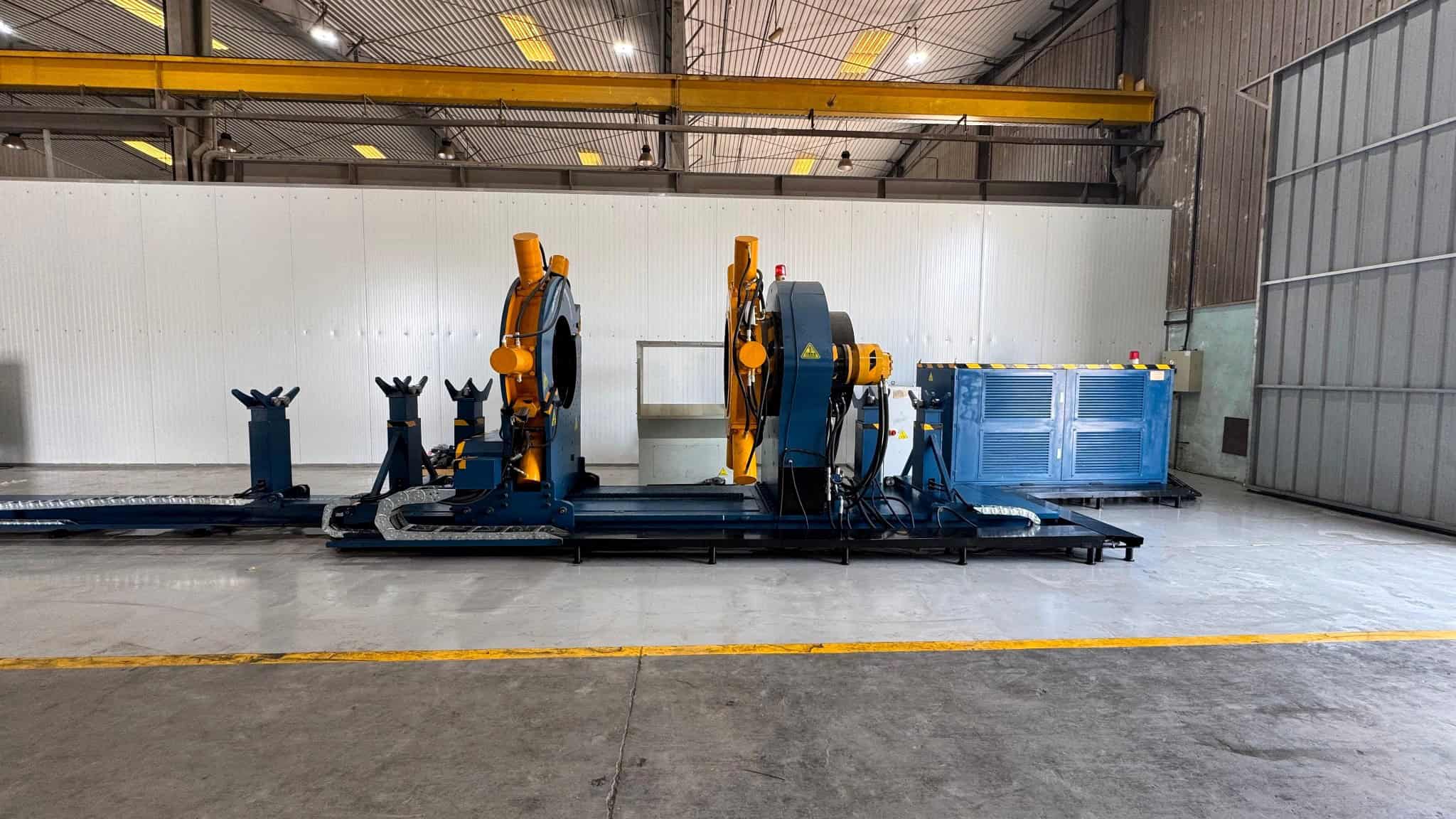
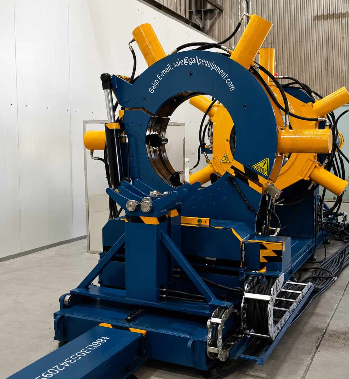
A torque-monitoring system can be used with different make-up equipment. In a workshop or threading facility, a hydraulic bucking unit combines workpiece support, clamping, controlled rotation, torque application, live curve review, and report generation in one fixed work cell. That integration is useful when the shop handles repeated casing, tubing, coupling, pup-joint, drill-pipe, or tool-service work.
The machine does not replace the procedure. It creates a more controlled environment in which the procedure can be executed and documented. The buyer should evaluate the complete system: OD and torque range, support arrangement, jaw options, rotation control, operator interface, calibration plan, reporting fields, data ownership, and after-sales support.
Safe product conclusion: Galip hydraulic bucking units can be configured for OCTG make-up workflows that require controlled rotation, torque-turn monitoring, and traceable report output.
What to ask when specifying an OCTG torque-monitoring system
- Which products will be processed: casing, tubing, couplings, pup joints, drill pipe, premium connections, or mixed assemblies?
- What are the minimum and maximum OD, typical torque, peak torque, workpiece length, and workpiece weight?
- Which connection-owner criteria must the system display or evaluate, and who controls revision updates?
- How will the operator identify the job and joint before starting the record?
- What curve, result, exception, reviewer, and witness fields must appear in the report?
- Can the buyer export reports in the required format and retain ownership of the job data?
- How are user permissions, parameter changes, and deleted or remade records controlled?
- What calibration, verification, maintenance, and spare-parts plan is included?
- How does the work cell support alignment and reduce slippage or surface marking?
- Can the supplier demonstrate the complete workflow during factory acceptance testing: setup, monitoring, hold point, report saving, retrieval, and backup?
- What training is provided for operators, supervisors, QA personnel, and maintenance technicians?
- What remote support and local hydraulic/electrical support will be available after installation?
A practical 30-day improvement plan
| Timing | Action |
|---|---|
| Days 1-5: Map the current process | Collect the current work instructions, torque sources, report templates, calibration records, file-naming habits, and common exception types. Follow one joint from receiving to release and note where information is lost. |
| Days 6-10: Standardize the record | Define mandatory fields, job naming, joint identity, operation mode, procedure revision, exception status, and storage location. Make the minimum report understandable without asking the operator to remember the job. |
| Days 11-15: Define hold points | Agree on who can stop the job, what curve or physical observations require review, who approves a remake, and how the original event is preserved. |
| Days 16-20: Train with real examples | Use anonymized normal and abnormal records from the shop. Ask operators to explain what they saw physically and how it appears in the curve. Avoid training only from a generic perfect graph. |
| Days 21-25: Start batch review | Review the first three joints and selected later records from repeated jobs. Look for drift after shift changes, compound changes, tooling changes, or machine stops. |
| Days 26-30: Audit retrieval | Select several completed jobs and ask the team to retrieve the correct report, official procedure revision, exception note, and reviewer sign-off. Fix the filing system while the problems are still small. |
Frequently asked questions about torque monitoring for OCTG pipes
Is final torque enough for OCTG connection acceptance?
Not always. Final torque shows where the operation ended, but it does not show whether the connection reached that point through a smooth, stable, and procedure-compliant path. The approved connection procedure determines the acceptance criteria.
What is the difference between torque monitoring and torque-turn monitoring?
Torque monitoring records resistance. Torque-turn monitoring records resistance together with angular movement. The combination provides more context about how the connection progressed.
Can one torque value be used for every pipe of the same OD?
No. Torque depends on the full product and connection definition, including size, weight, grade, connection family, component combination, and official procedure. Use the latest approved product data.
Should a questionable joint be made up again immediately?
Not without following the approved hold and review process. Preserve the first record, identify the joint, inspect the setup and connection, document the decision, and obtain the required approval before a remake.
What makes a torque report traceable?
It must be connected to the correct job and physical joint, show the controlling procedure, preserve the curve and result, record exceptions, identify the responsible people, and remain retrievable.
How often should torque-monitoring equipment be calibrated?
The interval should follow the manufacturer’s instructions, the workshop quality system, customer requirements, usage, environmental exposure, and calibration history. Operators should also perform the required pre-use readiness checks.
Can torque monitoring prevent all thread damage?
No. Monitoring supports early detection and better evidence, but thread protection also depends on inspection, cleanliness, compound, alignment, jaw selection, handling, speed, and operator discipline.
What should a buyer request before purchasing a torque machine?
Request a workflow demonstration and sample report, not only a maximum torque figure. Confirm OD range, normal and peak torque, support, jaws, control, reporting, calibration, training, spares, data ownership, and factory acceptance test scope.
Related reading: real-time torque-turn monitoring systems, casing coupling make-up controls, and OCTG connection integrity after the mill. Browse more technical guides.
Final thought: monitor the process, not just the number
A reliable OCTG connection program does not ask only whether the machine reached torque. It asks whether the correct joint was prepared, supported, made up under the approved procedure, reviewed as a complete event, and released with a record that can still be trusted later.
The strongest monitoring systems connect four things: the physical setup, the torque-turn signature, the identity of the joint, and the decision made by the operator or QA team. When one of those links is missing, the report becomes weaker. When all four are present, torque monitoring becomes part of the workshop quality system rather than a screen beside the machine.
Need a torque machine configured for your OCTG program?
Send Galip your product types, OD range, typical and peak torque, connection families, reporting format, daily output, power supply, and workshop layout. The engineering team can prepare a practical configuration and sample report for review.
View Galip hydraulic bucking units Send your requirements or write to sales@galipequipment.com.
Sources
- American Petroleum Institute — API Specification 5CT (11th Edition; Monogram effective Jan 2025). api.org
- TenarisHydril — OCTG product datasheets and mixed-assembly torque calculator. dcp.tenaris.com
- Galip Equipment — hydraulic bucking-unit capabilities, torque-turn display, and PDF/Excel reporting.
If the joints are made up outside your shop, the same record standards apply to the vendor — see third-party torque turning and what its reports must prove.
Expert Consultation
Need more information on optimizing your equipment performance? Our engineering team is available for technical consultations.
Request a Quote
Tell us about your requirements and our engineering team will prepare a detailed proposal with specifications, pricing, and delivery timeline.
