
Non-Magnetic Drill Collar Spacing: How Much NMDC You Need
Non-magnetic drill collar spacing is calculated from inclination, azimuth and your magnetic location – not a fixed length. Here is how to size it and keep azimuth error under 0.25 degrees.
Two rigs run the same bottom-hole assembly with the same length of non-magnetic collar. One gets clean surveys. The other has an azimuth that drifts by more than a degree. Nothing is wrong with either string. They are drilling in different places, in different directions, and that is enough to change the answer.
How much non-magnetic drill collar spacing do you need?
There is no single length. Non-magnetic drill collar spacing is calculated from three things: hole inclination, hole azimuth, and your geographic position on the earth’s magnetic field. The industry target is to keep magnetic azimuth error at or below 0.25 degrees. The same collar length that achieves that in one field can fall short in another.
At a glance
| What it controls | How much drill-string magnetism reaches the MWD magnetometers |
| Error target | Magnetic azimuth error at or below 0.25° is the common “good measurement” threshold |
| Depends on | Inclination, azimuth, magnetic dip and field strength at your location |
| Worst case | Drilling close to east or west, at higher magnetic dip |
| Zero-error case | Near vertical, or pointing at magnetic north or south |
| Also depends on | Where the sensor sits within the non-magnetic string, not just total length |
| Defeated by | A collar whose material is not actually magnetically clean |
Why the drill string corrupts azimuth in the first place
An MWD magnetometer measures the earth’s magnetic field and works out where north is. Steel drill collars above and below the sensor carry their own magnetism, largely along the axis of the string. That axial field adds to the earth’s field, and the sensor cannot tell the two apart. It reports the sum.
Distance is the only practical defence, and it is a steep one. Magnetic influence falls with the square of distance. A field of 10,000 gamma at 2 inches from the source is roughly 2,500 gamma at 4 inches and about 625 gamma at 8 inches. Doubling the separation quarters the interference, which is why the fix is length rather than shielding.
That is the entire purpose of non-magnetic drill collar spacing: put enough magnetically transparent material between the steel and the sensor that what remains is below the error you are prepared to accept.
Why the same collar length gives different results in different fields
Axial string magnetism acts along the hole. Whether that corrupts your azimuth reading depends on how the hole is oriented relative to the earth’s field.
Point the string at magnetic north and the interference lies along the same axis as the field you are measuring. It changes the magnitude slightly but not the direction, so azimuth survives. Drill near vertical and the same protection applies for a different reason. Turn the hole east or west, though, and the interference now sits across the field you are trying to read. That is where azimuth error appears, and it is why the east-west leg of a pad often surveys worse than the north-south leg with identical hardware.
Geography then multiplies it. Magnetic dip is shallow near the equator and steep near the poles, and total field strength varies too. Both feed the calculation. A crew moving from one basin to another with the same BHA standard is changing an input without changing the hardware, and current field values come from a model such as the NOAA World Magnetic Model.
| Factor | Effect to consider | What the team should use for a decision |
|---|---|---|
| Hole azimuth | Error peaks near east-west, approaches zero near magnetic north-south | Size for the worst azimuth the well plan actually contains |
| Inclination | Near-vertical holes are tolerant; error grows as the hole builds angle | Use the highest planned inclination, not the average |
| Magnetic dip at the location | Steeper dip generally demands more separation | Take current values from a magnetic model for the field, not a default |
| Sensor position in the string | Spacing is expressed as a proportion of total non-magnetic length | Confirm where the MWD sensor sits, not just how many collars are run |
| Steel proximity above and below | Both directions contribute; a short pup below can undo length above | Check the whole assembly, including subs and stabilisers |
| Collar material condition | Cold work or contamination raises permeability locally | Verify the collar is still magnetically clean, not just labelled non-mag |
What happens when the string is too short
Error does not creep in gently. Because interference falls with the square of distance, it also rises with the square as you shorten the string. A common estimating relationship expresses the expected error as 0.25 multiplied by the square of the recommended length divided by the square of the actual length.
Run 80% of the recommended length and the estimate lands near 0.39°. Run half, and it is around one degree. That is the practical shape of the problem: shaving one collar to save rig time does not cost you a proportional amount of accuracy, it costs considerably more.
An azimuth error of a degree does not sound dramatic until it is projected. Positional uncertainty grows with measured depth, and the ellipse around your wellbore widens accordingly. In a congested field with offset wells, that widening is the difference between a comfortable separation factor and a hold on drilling ahead. Guidance on how survey error is modelled and reported is maintained by the Industry Steering Committee on Wellbore Survey Accuracy.
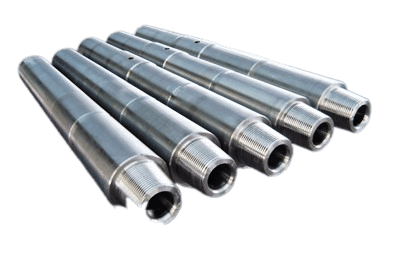
The collar has to actually be non-magnetic
Everything above assumes the material is doing its job. Non-magnetic collars are austenitic alloys chosen for low magnetic permeability, and permeability is a property that can be damaged after the collar leaves the mill.
Cold work raises it. So does heavy local machining, hard banding applied without control, and in some cases corrosion pitting that has been dressed out aggressively. A collar stamped non-magnetic that has been repaired in a yard without permeability checking is not necessarily still magnetically clean, and the survey has no way of telling you politely. It simply reads slightly wrong.
This is why permeability is specified and measured rather than assumed, typically at or below about 1.01 relative permeability, with the exact figure confirmed against your own specification. It is also why non-magnetic drill collar spacing calculations should be paired with material verification: the arithmetic assumes transparency the hardware has to deliver. Galip manufactures these collars and controls that property through material selection and machining discipline, which is covered on the non-magnetic drill collar product page.

When more collar is not the answer
Length is the blunt instrument. It is not always the right one, and in some situations adding collars buys very little.
| Situation | Why more length may not help | What to look at instead |
|---|---|---|
| Drilling close to magnetic north or south | Axial interference barely affects azimuth in this orientation | Standard spacing is usually sufficient; verify rather than extend |
| Near-vertical hole | Geometry already protects the reading | Inclination accuracy and toolface, not collar count |
| Error persists despite ample length | Points to the collar material or a hot spot, not the spacing | Permeability check on the collars in the string |
| Very long BHA, limited rig time | Handling risk and cost rise with every joint | Axial correction and multi-station analysis, agreed with the survey provider |
| Only one leg of the pad surveys badly | Consistent with azimuth dependence, not a hardware fault | Compare error against hole direction before changing the string |
Correction techniques deserve a note. Short-collar methods that mathematically correct for axial interference are established and can reduce the length required, but they are a survey-provider capability with their own assumptions and QC requirements. They are a decision to be made with whoever owns your survey programme, not a way to quietly run less collar.
Specifying and checking the string
| Check | What to confirm | Action when it does not match |
|---|---|---|
| Required length for this well | Calculated from planned inclination, azimuth and field location | Recalculate for the worst case in the plan, not the average |
| Sensor position within the string | Where the magnetometers sit as a proportion of total length | Reposition before adding collars; placement is often the cheaper fix |
| Steel below the sensor | Bit sub, motor, stabiliser contributions | Account for both directions in the calculation |
| Collar permeability | Measured, not inferred from a stamp or a paint colour | Quarantine and check any collar with unknown repair history |
| Connection and repair history | Hard banding, weld repair, heavy re-cut | Re-verify permeability after any of these |
| Survey QC at the wellsite | Total field, dip and gravity checks against expected values | Investigate before accepting the survey, not after the section |
The wellsite checks in that last row matter more than they are given credit for. Comparing measured total field and dip against the expected model values at that location is the fastest way to catch a magnetically contaminated string, and it costs nothing but attention.
Reading the wellsite survey QC numbers
Every magnetic survey carries three self-checks, and they are the cheapest quality control available on the rig. Measured total magnetic field, magnetic dip angle and total gravity are each compared against the expected value for that location and depth. When one drifts, the survey is telling you something before the directional plot does.
| Observation | Possible contributing factors | What to verify first |
|---|---|---|
| Total field reads high, dip reads high | Axial interference from the string, often insufficient non-magnetic length | The spacing calculation for this hole direction |
| Total field normal, dip off | Cross-axial interference, or a local hot spot near the sensor | Nearby components and any recently repaired collar |
| Error appears only on one hole direction | Classic azimuth dependence, not a hardware fault | Compare against the well plan before changing the BHA |
| Gravity check out of tolerance | Accelerometer or tool problem, not magnetics | Tool health; non-magnetic drill collar spacing is not the cause |
| Everything drifts after a bit trip | A component swapped into the string carries magnetism | What changed in the assembly, in both directions from the sensor |
| Values fine, azimuth still disputed | Reference model or declination applied incorrectly | The magnetic model, date and coordinates in use |
The fourth row is worth dwelling on because it is where time gets wasted. A gravity failure is an accelerometer story, and no amount of additional collar will change it. Separating magnetic problems from tool problems at the wellsite prevents an expensive round of BHA changes aimed at the wrong target.
Where the calculation actually comes from
Nobody derives this by hand at the rig. The requirement is produced either from published spacing charts, which index required length against inclination, azimuth and magnetic region, or from software supplied by the survey provider that takes the same inputs and returns a length with a stated expected error.
Both routes need the same information, and both are only as good as the inputs. The two most common input errors are using an average inclination rather than the maximum in the plan, and carrying a magnetic region assumption over from a previous field. Neither shows up as an obvious mistake. They show up later as an azimuth that will not reconcile.
If your operation runs the same BHA standard across several basins, that standard is worth re-checking against each location rather than treated as settled. The hardware does not change, but the requirement does.
Proof and documentation
For a collar, the useful record is material certification with permeability stated as a measured value, the mechanical properties, and the inspection history including any repair. A stamp alone proves the intent of the manufacturer, not the current condition of the steel in your hand.
Galip supplies non-magnetic collars along with the related downhole hardware where magnetic cleanliness matters, including sonde housings for directional and utility work. For the wider service-centre context see the downhole tool service centre guide, and for adjacent BHA components, drilling motors and mud motor components.
Collars are not the only BHA component bought against a code rather than a description. The same problem appears when ordering bits, where the IADC code for tricone bits gets copied from one purchase order to the next without anyone checking that the formation still matches.
Frequently asked questions about non-magnetic drill collar spacing
Is there a standard non-magnetic drill collar length?
No. Charts and rules of thumb exist, but the requirement is calculated from planned inclination, azimuth and the magnetic field at your location. A length that is comfortable in one basin can be short in another with identical hardware.
Why is east-west drilling worse for azimuth error?
Drill-string magnetism acts along the hole axis. Pointing north or south, that interference lies along the field being measured and barely disturbs direction. Pointing east or west, it sits across the measurement, which is where azimuth error appears.
What azimuth error is acceptable?
0.25 degrees is widely used as the threshold for a good magnetic measurement. Tighter requirements apply in congested fields or close to offset wells, and the number should come from your anti-collision requirements rather than a default.
Does the sensor position matter, or just total length?
Both. Spacing is normally expressed as a proportion of the total non-magnetic length, because steel above and below the sensor both contribute. Repositioning the sensor within the string is often cheaper than adding another collar.
Can a non-magnetic collar become magnetic?
Its permeability can rise. Cold work, heavy machining, hard banding and some repair practices can all raise local permeability. The collar is still the same alloy, but it is no longer performing as designed, and only measurement will reveal it.
Can I run shorter collars and correct the survey instead?
Sometimes. Axial correction and multi-station analysis are established techniques that can reduce the length required, but they depend on your survey provider’s capability and QC. Agree it with them in advance rather than treating it as a field decision.
How do I check the string is clean at the wellsite?
Compare measured total magnetic field, dip angle and gravity against the expected values for that location. Disagreement beyond the accepted tolerance suggests interference or a contaminated collar, and it should be resolved before the survey is accepted.
Getting collars specified and quoted
Non-magnetic drill collar spacing determines how much you need; the specification determines whether it works. Send the following and the engineering team will return a configuration matched to your BHA:
- Collar OD and ID, and connection type required
- Length per joint and number of joints
- Maximum relative permeability you specify
- Material grade or alloy requirement
- MWD tool type and sensor position in the string
- Planned inclination and azimuth range for the wells
- Field or basin, so magnetic conditions can be considered
- Inspection and certification package required
Before you run the string: a short checklist
- Was the required length calculated for this field, or carried over from the last one?
- Does the calculation use the worst inclination and azimuth in the plan?
- Do you know where the sensor sits within the non-magnetic string?
- Has steel below the sensor been included, not just above?
- Is there a measured permeability figure for these specific collars?
- Has any collar in the string been repaired, hard banded or heavily machined since it was last checked?
- Are wellsite total-field and dip checks part of the survey acceptance procedure?
If the first and fifth have no clear answer, start there. Most magnetic survey problems trace back to a calculation carried over from a different field, or to a collar that is no longer as magnetically clean as its stamp suggests.
Expert Consultation
Need more information on optimizing your equipment performance? Our engineering team is available for technical consultations.
Request a Quote
Tell us about your requirements and our engineering team will prepare a detailed proposal with specifications, pricing, and delivery timeline.