
Coiled Tubing Downhole Tools: The 5 Tests Before Every Run
A CT string works blind, so everything is proved at surface: connector pull tests, check valves, disconnect release values, motor curves and the records behind them.
Coiled tubing downhole tools are the components run beneath the reel: the connector that grips the tubing, dual check valves that hold the well back, a disconnect that releases on command, and the working tools below them. Because a CT job is a single unseen trip, every one of those functions is proved on a bench at surface, not discovered downhole.
At a glance
| What the toolstring is | The bottom hole assembly hung from the coiled tubing: connector, check valves, disconnect, then motors, oscillators, shock tools and nozzles as the job demands |
| Why testing dominates | The tubing does not rotate and nobody sees the tools again until the job ends. Whatever was wrong at surface stays wrong for the whole run |
| The five tests | Connector pull test · check-valve function and pressure test · disconnect release verification · working-tool function test · assembled-string integrity check |
| Who runs them | The CT service company’s base workshop, before mobilisation, with each result recorded against the tool’s serial number |
| Decision this page supports | Auditing a CT contractor’s pre-job test records, or specifying the bench a base needs to produce them |
The string nobody sees again
A drillpipe assembly can be rotated, worked and reasoned about from surface. A coiled tubing string cannot: it goes in the hole in one continuous run, it cannot rotate, and every tool below the reel does its work blind. If the connector slips, the string is lost. If the check valves leak, the well flows up the tubing. If the motor stalls low, the milling job fails at depth with the day rate running.
That asymmetry explains the culture of coiled tubing tool testing. There is no second look downhole, so all verification is loaded onto the bench at the base. The same principle already governs drilling jar bench testing — prove the release on a calibrated frame, because the alternative is proving it with a fishing job — and coiled tubing simply applies it to every component in the string.
The standard toolstring, top to bottom
| Component | What it does | What the bench must prove |
|---|---|---|
| CT connector | Grips the end of the coiled tubing and carries the whole string’s weight and torque — grapple, dimple or set-screw designs | A recorded pull test on the installed connector, to the load the job design specifies, plus pressure integrity through it |
| Dual check valves | Two flapper or ball checks in series that stop well fluids flowing up the tubing — a primary well-control barrier | Function of each flapper and a pressure test from below, per valve, recorded individually |
| Release / disconnect tool | Lets the crew drop the string below it on command, usually by dropping a ball, when the tools below are stuck | The actual release value against its rating, and re-verification after redress |
| Motorhead assembly | Connector, checks and disconnect packaged as one crossover unit at the top of the working string | Each internal function individually, then the assembly end to end |
| Downhole motor | Converts pumped fluid into rotation for milling, cleanouts and drilling work below the CT | A function run: pressure against flow, free and loaded speed, and stall behaviour, logged as curves |
| Hydraulic oscillator / agitator | Pulses the string to break friction and extend reach in deviated wells | Operating pressure drop and pulse behaviour at rated flow, compared with the tool’s baseline |
| Shock tool / CT jar | Delivers impact when the string below is stuck | Firing load, measured on the bench, the same discipline as any jar |
| Nozzles and circulation subs | Jetting, cleanouts, fluid placement | Open bore, correct nozzle sizes fitted, pressure drop sane at plan flow |
The connector pull test: cheap insurance for the whole string
Everything hangs from the connector, and the connector’s grip depends on how well it was installed on that particular cut of tubing on that particular day. So the test is refreshingly direct: after installation, the connector is pulled against the tubing at a recorded load and held, before any tool is trusted to it. A connector that slips on the bench cost an hour. A connector that slips downhole costs the toolstring, a fishing operation and the job.
The load applied is set by the job design — string weight, expected overpull, a margin — and the record matters as much as the pull. Serial number, tubing size, measured load, hold, date, operator. When a customer’s representative asks how the crew knows the string will not part at the connector, the answer is a line in a file, not an assurance.
Function testing the working tools
Motors, oscillators and shock tools are performance tools, and performance is a curve, not a pass mark. A motor’s health shows in the relationship between flow, pressure and speed — a tired power section takes more pressure to do the same work and stalls earlier. An oscillator’s health is its pressure drop and pulse signature at rated flow. A shock tool’s is the load at which it actually fires. In each case the bench measures the same things a motor dynamometer test measures at larger scale: applied fluid in, measured mechanical behaviour out, logged against the tool’s baseline.
The baseline is the quiet hero. A single test proves the tool works today; a filed history of tests shows the trend — the pressure creeping up job by job, the release load drifting — and lets the base pull a tool for service one job before it fails rather than one job after. That is the same argument that puts logged curves ahead of gauge glances on a jar test bench, and it is why a test bench without data logging is half a bench.
What the bench itself needs to be
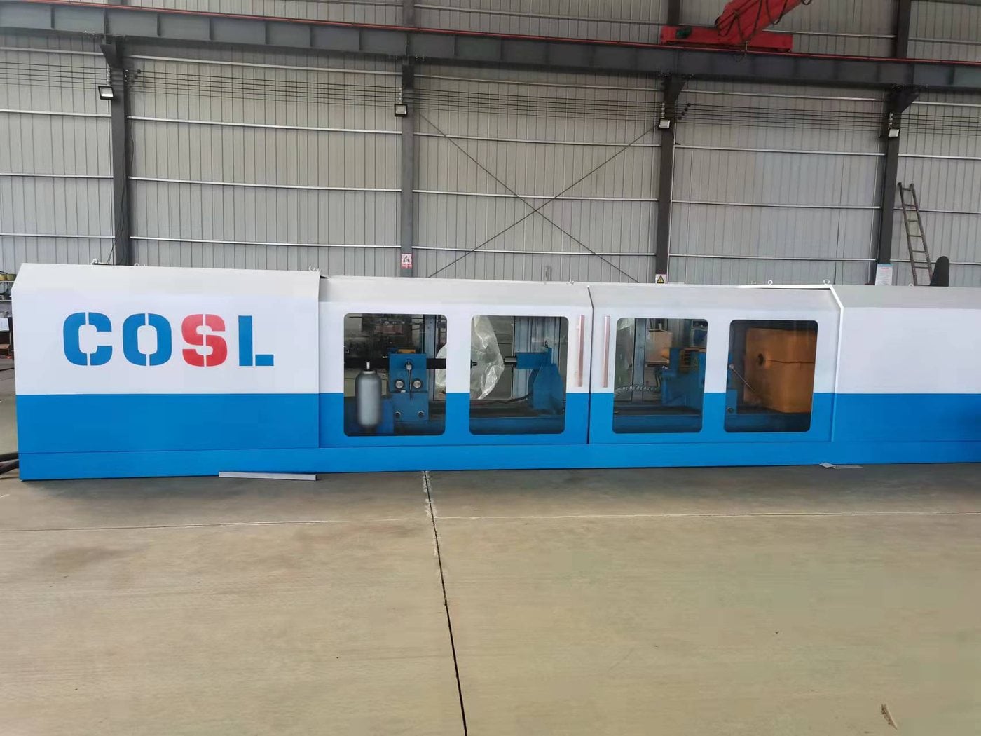
The requirements follow from the tools. Horizontal, because CT tools are long, slender and handled by small crews. Clamping that holds the tool without damaging it, with the working area guarded, because several of these tests store real energy. A pull axis with a calibrated load cell for connectors, disconnects and shock tools. A pressure loop with measured flow for checks, motors and oscillators. And instrumentation that records — pressure, flow, force, torque, speed — into a report the customer can audit, tied to the tool’s serial number.
A base that already tests jars and lifting gear will recognise the architecture: it is the same calibrated load-frame family that runs sling proof load tests, with a hydraulic function loop added. Galip builds benches in this family against the buyer’s actual tool list — sizes, test loads, pressures and report format — rather than a fixed catalogue machine, and the specification conversation starts from that list.
Reading a contractor’s test records: the audit table
| Check | What to confirm | Action when it does not match |
|---|---|---|
| Connector pull test | A recorded load and hold for the connector as installed for this job, not a previous one | No record, or a record older than the last connector installation: re-test before mobilising |
| Check valve tests | Each valve tested individually, from below, with the result per serial number | A single line covering “checks OK” for the pair: ask which valve, at what pressure, and watch the answer |
| Disconnect release value | The measured release against rating, re-verified after any redress | A brochure figure quoted instead of a measured one: the tool has not been tested |
| Motor / oscillator curves | Logged pressure-flow behaviour compared against the tool’s own baseline | Pass marks with no curves: the bench has no logging, and trend information does not exist |
| Calibration chain | The bench’s load cell and pressure instruments in calibration on the test date | Expired calibration invalidates every certificate it produced — treat affected tools as untested |
| Serial-number traceability | Every record tied to the physical tool, which carries the same number | Records by tool type rather than serial: the file describes the fleet, not the string going in your well |
Where this fails in practice
The pattern is rarely a missing test; it is a test that stopped meaning anything. The bench is uncalibrated and nobody noticed. The pull test was done on the connector before it was cut off and re-installed. The disconnect was redressed at the rig and the shop’s release record no longer describes the tool in the string. The motor passed, but nobody kept the curve, so the slow decline across five jobs was invisible until it stalled on the sixth. Each failure traces to the same root: treating the record as paperwork rather than as the product. The service-centre discipline — one serial number, one file, from receiving to release — is what keeps a testing programme honest after the novelty wears off.
Frequently asked questions
What tools make up a coiled tubing BHA?
From the tubing down: a connector gripping the coil, dual check valves as the well-control barrier, a release or disconnect tool, then the working tools the job needs — downhole motor, hydraulic oscillator, shock tool, jetting nozzles or circulation subs. The upper three are often packaged as one motorhead assembly.
What is a coiled tubing connector pull test?
After the connector is installed on the tubing, it is pulled at a recorded load and held to prove the grip before the string is trusted to it. The load comes from the job design — string weight plus expected overpull and margin — and the result is recorded against the connector and the installation.
Why are two check valves run instead of one?
They are a well-control barrier, and barriers are doubled. Two independent checks in series mean a single failed flapper does not open the tubing to well flow. Each valve is function-tested and pressure-tested individually before the job, because a pair tested together can hide one dead valve behind the other.
How is a coiled tubing motor tested before a job?
On a bench with a pressure loop: fluid is pumped at measured flow while pressure and output speed are logged, free and under load, including stall behaviour. The curves are compared with the motor’s own baseline, so a power section that is fading shows as a trend before it fails in the hole.
What does a disconnect tool release test prove?
That the tool actually releases at its intended value — usually verified after every redress. The crew relies on that number on the day the string sticks: a disconnect that releases high wastes time and risks the tubing, one that releases low can drop the string when it should have held.
What should a CT tool test certificate contain?
The tool’s serial number, what was tested and how, the measured values — loads, pressures, release points — with logged curves where the test produces them, the bench’s calibration reference, and date, place and operator. A certificate without measured values or a calibration reference is a formality, not evidence.
Can one bench test connectors, disconnects, motors and oscillators?
Yes, if it combines a calibrated pull axis with a metered pressure loop and records both. Horizontal benches built this way handle the pull tests and the function tests on one frame, which is why CT bases specify them against their actual tool list rather than buying separate rigs per tool.
Specify the bench from the tool list
A test bench is defined by the fleet it must prove, so send the list, not a guess: tool types and OD range · maximum pull-test load · working and test pressures with required flow · which tools need torque and speed measured · report format your customers audit · the calibration regime available locally. Write to the contact page or sales@galipequipment.com and the reply will be a specification against that list, with approved figures stated rather than assumed.
Before the string leaves the base: the checklist
- Connector pull-tested as installed for this job, at the design load, with the record filed.
- Both check valves function-tested and pressure-tested individually, per serial number.
- Disconnect release value measured, and re-measured after any redress — never quoted from the brochure.
- Motor curves logged at test flow and compared against that motor’s baseline, not just passed.
- Oscillator pressure drop and pulse behaviour checked at rated flow.
- Shock tool firing load measured on the bench.
- Nozzle sizes verified against the programme and bores confirmed clear.
- Assembled string pressure-checked end to end before it ships.
- Bench load cell and pressure instruments in calibration on every test date.
- Every record tied to a serial number the customer can read on the tool itself.
Expert Consultation
Need more information on optimizing your equipment performance? Our engineering team is available for technical consultations.
Request a Quote
Tell us about your requirements and our engineering team will prepare a detailed proposal with specifications, pricing, and delivery timeline.
