
Drilling Jar Maintenance: 11 Inspection Points Before Bench Testing and Return to Service
A practical drilling jar maintenance checklist: identity, cleaning, connections, mandrel, seals, latches, wear measurement, parts control, reassembly, and the pre-test readiness review.
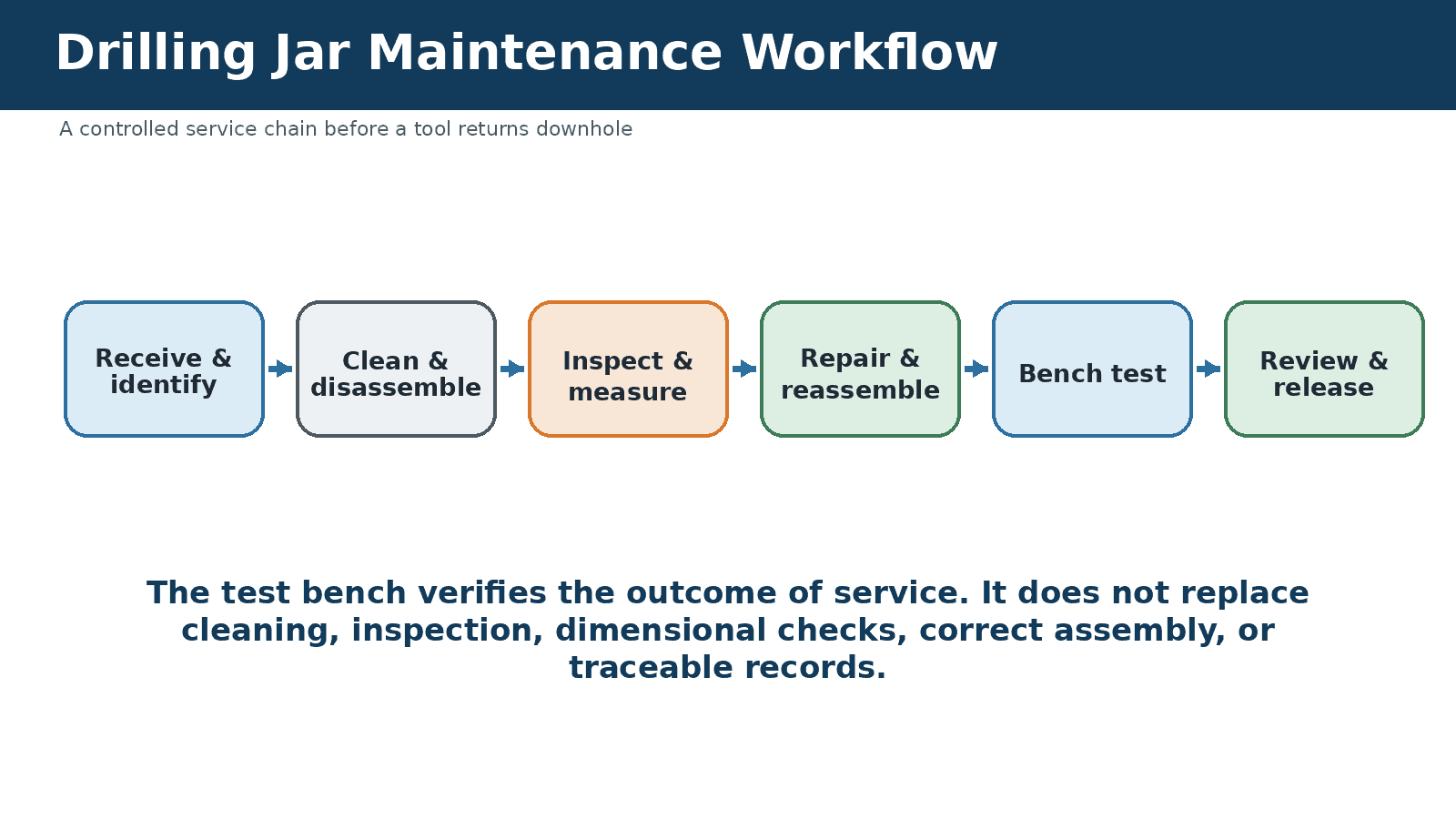
Quick answer: Drilling jar maintenance is a controlled chain, not a single repair: confirm identity and history, clean the tool, inspect connections, mandrel, body, seals and latches, measure wear against approved limits, control replacement parts, reassemble under procedure, and only then verify the result on a calibrated test bench. The eleven inspection points below decide whether the jar is ready for that final test.
A drilling jar is easy to overlook when it is sitting quietly in a service bay. It has no engine sound, no rotating bit and no visible production output. Yet when a drillstring becomes stuck, the jar may be the tool expected to create the impact needed to recover movement. That makes the quality of drilling jar maintenance more than a workshop housekeeping issue. It is part of drilling-risk control.
The difficulty is that a jar can look acceptable from the outside while still carrying internal wear, contamination, seal problems, surface damage or an incorrect release condition. Cleaning the body and repainting the tool may improve its appearance, but appearance alone does not confirm that it will latch, release, stroke and reset as intended. A reliable service process therefore needs several layers: identity control, disassembly, inspection, measurement, approved repair, correct reassembly and a final controlled bench test. Connections that are broken out for inspection go back together on a bucking unit with the make-up torque recorded, so the reassembled jar carries a connection record as well as an inspection record.
This drilling jar maintenance guide focuses on the stage before the bench test. It explains the inspection points that help a service team decide whether the tool is ready to be tested, needs additional repair, or should be held from service. The article is not a substitute for the jar manufacturer’s manual, approved service procedures or customer-specific acceptance criteria. Instead, it gives workshop managers, technicians and buyers a practical framework for understanding what a disciplined drilling jar service process should contain.
Why Drilling Jar Maintenance Deserves Its Own Workflow
Drilling jars operate in a demanding part of the drillstring. They may be exposed to tensile and compressive loading, torque, vibration, drilling fluid, solids, temperature changes and long periods in the well. Their function also depends on internal mechanisms that must move, delay, latch or release in a controlled way. Because of that combination, the service process cannot be reduced to a generic wash-and-grease routine.
Odfjell Technology describes the drilling jar as a key tool for helping recover a stuck drillstring and notes that incorrect placement or operating conditions can contribute to poor performance or fatigue. Weatherford service guidance for some jar designs calls for washing mud from the polished mandrel and inspecting it for corrosion, pitting or coating damage after the tool comes out of the hole. Those examples point to a larger rule: external condition, internal condition and operating history all matter before a jar returns to service.
Good drilling jar maintenance creates a controlled answer to three questions. First, is the tool correctly identified and suitable for the next job? Second, are its components within the approved service limits? Third, does the assembled tool demonstrate repeatable functional behavior on a calibrated test system? If any one of those questions is unanswered, the release decision remains weak.
The Difference Between Inspection, Service and Testing
The words inspection, service and testing are often used together, but they do not mean the same thing. Inspection is the process of finding and measuring condition. Service is the controlled work performed to restore the tool in accordance with an approved procedure. Testing is the functional verification that follows service.
A visual inspection may reveal impact marks, leaking fluid, damaged connections or a corroded mandrel. Dimensional checks may reveal wear that is not obvious by sight. Magnetic particle inspection may be required on suitable parts when the approved service scope calls for detection of surface or near-surface discontinuities. None of those activities proves the complete jar will release at the intended load after assembly.
In the same way, a successful bench test does not prove that every component received the right inspection if the workshop has no service record. The strongest workflow connects the findings, the repairs and the final test. The result is not simply a tool that moved on a machine; it is a tool with a defensible history.

The Drilling Jar Maintenance Checklist: 11 Inspection Points
1. Confirm Tool Identity and Service History
Every drilling jar inspection should begin with identity. The service team should confirm the serial number, tool size, model, connection type, service owner and available operating history. If the identification is unclear, the tool should not be treated as an ordinary unit that can be rebuilt from memory.
History can change the inspection priority. A jar returning from a high-temperature job, a severe stuck-pipe event or an unusually long run may require a different review from a tool that completed a short, routine service. The workshop should record known hours, job conditions, reported performance, previous repairs and any customer complaint. A statement such as “did not fire” is not yet a diagnosis, but it is an important starting point.
Identity control also prevents records from being attached to the wrong tool. A complete service file should follow the same serial number from receiving through disassembly, measurement, reassembly, bench testing and release. The same serial-number discipline applies to the workshop’s own lifting gear — wire rope sling load testing runs on the same certificate logic.
2. Clean the Tool Before Judging Its Condition
Inspection through mud, grease and shop debris is unreliable. External cleaning should remove material that hides surface condition while following the manufacturer’s handling and environmental requirements. The goal is not cosmetic appearance. It is visibility and contamination control.
Particular attention is commonly given to the polished mandrel, connection areas, shoulders, ports, exposed seals and places where fluid leakage may collect dirt. Cleaning should also prevent foreign material from being carried into the tool during disassembly. A clean service area, controlled parts trays and identification tags reduce the chance that small components are mixed between jobs.
Cleaning can also provide useful clues. Metal particles, unusual debris, degraded lubricant or contaminated fluid may indicate an internal condition that deserves closer investigation. Those observations should be documented before the evidence is washed away.
3. Inspect Pin and Box Connections
The connections are the interface between the jar and the rest of the bottom-hole assembly. Their condition influences safe handling, load transfer and future assembly. Inspection should cover thread form, shoulders, seal areas where applicable, dents, galling, corrosion, impact damage and contamination.
Connection acceptance should follow the applicable manufacturer and customer requirements. A service team should not invent its own repair limits or assume that every damaged thread can be dressed by hand. If machining, recutting or dimensional restoration is permitted, the work should be performed under an approved process and followed by the required inspection.
Protectors should remain part of the workflow. Clean, suitable protectors help prevent a serviced connection from being damaged between inspection, testing, storage and dispatch.
4. Examine the Polished Mandrel and Coated Surfaces
The polished mandrel deserves careful attention because its surface condition can affect sealing, guidance and movement. Weatherford guidance for certain drilling jars specifically calls for checking for corrosion, pitting and flaking of the coating after cleaning. Similar concerns apply more broadly, although the permitted limits and repair methods depend on the specific tool design.
Technicians should look for scoring, impact marks, embedded debris, worn coating, localized corrosion and handling damage. A fingernail-level scratch may appear minor, but only the approved service criteria can determine whether the surface remains acceptable. Polishing away evidence without measurement or authorization can make the condition harder to evaluate.
The inspection record should describe the location and extent of the finding, not merely say “mandrel checked.” Photographs with a scale can be useful when the customer or technical authority must review the condition.
5. Check the Body, Housing and Load-Carrying Components
The jar body, pressure housing, mandrel and other load-carrying components should be examined for impact damage, distortion, corrosion, cracks, thread damage and signs of abnormal contact. Some parts may require nondestructive examination under the approved service scope.
A workshop should distinguish between inspection methods. Visual examination can reveal obvious surface conditions. Dimensional measurement can show wear or distortion. Magnetic particle inspection can identify certain surface and near-surface discontinuities in suitable ferromagnetic components. One method does not replace another when the service specification requires both.
Calibration status matters here. A measurement written in a report is only meaningful when the instrument is suitable, identified and within calibration. The same principle applies to test benches later in the process.

6. Evaluate Seals, Leakage and Hydraulic Condition
Hydraulic jars depend on seals, fluid passages and metering elements that must work together. External seepage, fluid loss, damaged elastomers, contaminated fluid or incorrect assembly can change timing and release behavior. Mechanical jars have different internal mechanisms, but they still require controlled inspection of springs, latches, rollers, detents and wear surfaces according to their design.
Seal replacement should not become a blind routine. The removed parts and surrounding surfaces can reveal the reason for leakage or abnormal movement. A cut seal may point to assembly damage, while debris may indicate contamination. Hardened or degraded elastomers may reflect age, fluid compatibility or temperature exposure. The workshop should record what it sees rather than discarding the evidence immediately.
Fluid type, cleanliness, fill method and bleeding procedure must follow the approved tool instructions. The objective is to restore the designed hydraulic behavior, not simply to fill the body until it appears complete.

7. Inspect Latches, Detents, Splines and Guiding Features
The internal triggering and guiding features are central to how a jar stores and releases energy. Wear, contamination, deformation or incorrect assembly in these areas may contribute to early release, delayed release, unstable cycling or failure to reset.
During drilling jar maintenance, parts should be cleaned and inspected individually, with measurements compared against the approved limits. Contact patterns can be informative. Uneven wear may suggest misalignment, side loading or a component that has not been moving as intended. Splines and guides should be evaluated for wear and damage while preserving the geometry defined by the tool manufacturer.
A common workshop mistake is to treat free movement by hand as proof of correct operation. Hand movement can identify obvious binding, but it does not reproduce the load, timing and controlled stroke of a bench test.
8. Measure Wear Instead of Describing It Vaguely
Terms such as “slightly worn,” “looks good” or “acceptable by experience” are weak when a critical component has a defined limit. Dimensional inspection turns a subjective statement into a traceable decision.
The measurement plan should identify the feature, instrument, reference dimension, measured result, tolerance or service limit and disposition. Depending on the design, this may include diameters, clearances, lengths, connection features, stroke-related dimensions, wear surfaces and straightness checks.
Not every dimension belongs in a public checklist, because the correct values are model-specific and may be proprietary. What matters is that the workshop has controlled drawings or service specifications and uses them consistently.
9. Control Replacement Parts and Service Materials
A jar can pass visual inspection and still be assembled incorrectly if the wrong seals, springs, fluids, fasteners or replacement parts are used. Parts control is therefore part of drilling jar inspection, not a separate purchasing issue.
The service record should identify critical replacement parts and, where required, their batch or source. Parts should be protected from contamination and mixed-job handling. Elastomers and service fluids should be checked for compatibility with the intended temperature and operating environment.
When a tool is prepared for high-temperature service, for example, the required seal package or configuration may differ from a standard job. Odfjell notes that service-hour recommendations can also change in elevated temperature conditions. The lesson is broader than any single number: job conditions must influence the maintenance plan.
10. Reassemble Under a Controlled Procedure
Reassembly should follow the approved sequence, cleanliness requirements, lubrication instructions, torque values, orientation checks and safety controls. A clean inspection is wasted if the tool is damaged or contaminated during assembly.
Technicians should verify that components are installed in the correct orientation and that locking, latching or metering features are set as required. Assembly records should identify the technician, date, tool serial number, critical parts changed and any deviation approved by the technical authority.
After assembly, a preliminary movement or leak check may be required before the jar is mounted on the test bench. This check is not the final functional test; it is a readiness step intended to catch obvious assembly problems early.
11. Complete a Pre-Test Readiness Review
Before bench testing, the team should confirm that the jar, the test system and the test plan are ready. The tool identity must match the job record. Connections and clamping areas must be suitable for mounting. Supports must match the tool size and keep the load path aligned. The test instruments must have current calibration status and the correct capacity.
The test plan should state the direction of loading, expected release window, number of cycles, stroke or travel measurement, reset requirement and report fields. Acceptance values must come from the tool owner, manufacturer or approved service document, not from a generic internet table.
This readiness review protects both safety and data quality. A misaligned tool or incorrect support can introduce side load and distort the readings. A wrong range or unverified sensor can produce a clean-looking report that is still technically unreliable.

Why Bench Testing Is the Final Verification Layer
NOV describes downhole jar testers as systems used to test the operational condition of drilling and fishing jars. Forum Energy Technologies describes self-contained jar testers that apply tension and compression in direct axial alignment and can record pressure, stroke distance and time. These examples show why a dedicated test system is different from an improvised pull test.
A controlled test can verify release load, stroke, repeatability, reset behavior and, where the procedure requires it, response in both tension and compression. Multiple cycles are valuable because one successful release may hide unstable behavior. A repeatable result within the approved window provides stronger evidence than a single pass.
For readers who need the detailed sequence after maintenance is complete, Galip’s drilling jar testing procedure explains the bench-test workflow, curve review and test-record logic. Workshops evaluating the equipment itself can review the hydraulic drilling jar tester page for the typical role of controlled loading, instrumentation and reporting. The hydraulic drilling jar tester product page covers the machine itself: capacities, measurement, and reporting.
The important distinction remains: the bench test proves the outcome of service. It does not replace disassembly, inspection or correct repair. A tool that fails should return to the service process, not receive a convenient pass based on appearance.

Common Symptoms and What They May Suggest
A drilling jar troubleshooting process should begin with evidence, not assumptions. A jar that does not respond in the well may be affected by operating conditions, placement, applied weight, pump-open force, failure to cock, insufficient waiting time or an internal tool condition. Odfjell lists several of these operational causes when discussing a non-responding jar. That is why a field complaint must be translated into a structured inspection and test plan.
On the bench, an early release may suggest a worn or incorrectly set triggering mechanism. A release value that drifts across repeated cycles may point toward wear, contamination, seal behavior or inconsistent reset. Stick-slip movement may be associated with contamination, surface condition or lubrication issues. Leakage may indicate a seal, surface or assembly problem. These are troubleshooting clues, not universal diagnoses.
The service team should compare the load and travel traces with the approved baseline for the specific tool. Replacing parts based only on a general symptom can add cost without correcting the real problem.
What a Strong Drilling Jar Inspection Report Should Contain
A useful inspection report is more than a page with a pass stamp. It should allow another qualified person to understand what tool was serviced, what was inspected, what was found, what work was completed and why the final decision was made.
A practical report package may include tool identity, customer and job reference, received condition, visual findings, connection condition, dimensional results, nondestructive examination results where applicable, replacement parts, assembly record, bench-test settings, cycle results, calibration references, photographs and final disposition.
The report should also distinguish between measured facts and technical interpretation. For example, “0.20 mm wear measured at location X” is a fact. “Acceptable for service under document Y, revision Z” is the disposition. Keeping those two elements clear makes the record easier to audit.

How Better Jar Service Supports the Business
A disciplined drilling jar service process has business value beyond the workshop. It reduces the chance of releasing an unverified tool, creates clearer evidence for customers and helps technicians learn from repeated findings. It can also improve quotation accuracy because the workshop understands which repairs, replacement parts and tests are actually required.
For rental companies, traceable maintenance supports fleet control. For independent service shops, it strengthens customer confidence. For tool manufacturers, it helps connect design requirements with real service data. For drilling contractors, it reduces uncertainty before a critical tool enters the bottom-hole assembly.
The goal is not to promise that a maintained jar will solve every stuck-pipe event. Downhole performance also depends on placement, drilling conditions and correct operation. The goal is to ensure that the tool leaves the workshop with its condition verified as far as the approved surface process can reasonably demonstrate.
Drilling jar maintenance FAQ
How often should a drilling jar be serviced?
The correct interval depends on the tool model, operating hours, temperature, job severity, customer requirements and manufacturer recommendations. A fixed universal interval should not replace the approved maintenance program.
Is visual inspection enough?
No. Visual inspection is essential but cannot confirm all internal wear, dimensional condition or functional release behavior. The required combination of inspection methods depends on the tool and service scope.
What is the difference between drilling jar inspection and drilling jar testing?
Inspection evaluates component condition and dimensions. Testing verifies the assembled tool’s functional performance under controlled load.
Can one jar tester handle different tool sizes?
Many test systems are designed with adjustable supports, clamps or customer-specific bed lengths and load capacities. The actual range should be confirmed against the largest tool, maximum force, travel and reporting requirements.
What should be included in a jar test certificate?
Common fields include tool identity, test direction, release values, stroke or travel, repeated cycles, result, operator, date and calibration references. The exact content should follow the customer and service procedure.
Does a successful test mean no maintenance was needed?
No. Testing is the final verification after the service work. It does not prove what was inspected or replaced unless the maintenance record is linked to the test report.
Conclusion
Reliable drilling jar maintenance is not a single repair activity. It is a controlled chain that begins with tool identity and operating history, continues through cleaning, inspection, measurement, parts control and approved reassembly, and ends with repeatable functional testing.
The most useful workshop question is not simply, “Does the jar move?” It is, “Can we show that the correct tool was inspected, serviced, assembled and tested against the correct criteria?” That question produces better records, clearer release decisions and a more defensible service process.
A drilling jar may only be needed during a difficult downhole event, but the confidence behind that tool is built on the surface. The service bay, inspection process and test bench are where uncertainty should be found while it is still inexpensive to correct.
Sources
- NOV — Drilling and Fishing Jar Tester
- Forum Energy Technologies — Jar Testers and Automated Jar Testing Logging System (PDF)
- Odfjell Technology — Drilling Jar Placement: How to Get It Right
- Weatherford — Jars, Shocks and Accelerators (PDF)
- SPE/IADC — Performance Testing of Jars
Expert Consultation
Need more information on optimizing your equipment performance? Our engineering team is available for technical consultations.
Request a Quote
Tell us about your requirements and our engineering team will prepare a detailed proposal with specifications, pricing, and delivery timeline.
